


105501-01F
For more information, visit www.desatech.com
For more information, visit www.desatech.com
18
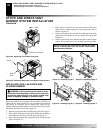
STOVE AND DIRECT-VENT BURNER SYSTEM INSTALLATION
Check Gas Type
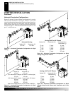
Installing Gas Piping To Stove/Burner System Location
STOVE AND DIRECT-VENT
BURNER SYSTEM INSTALLATION
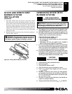
INSTALLING GAS PIPING TO STOVE/
BURNER SYSTEM LOCATION
Installation Items Needed
Before installing stove and burner system, make sure you have the
items listed below.
• external regulator (supplied by installer)
• piping (check local codes)
• sealant (resistant to propane/LP gas)
• equipment shutoff valve *
• test gauge connection *
• sediment trap
• tee joint
• pipe wrench
• approved flexible gas line with gas connector (if allowed by lo-
cal codes) (not provided)
* A CSA design-certified equipment shutoff valve with 1/8" NPT
tap is an acceptable alternative to test gauge connection. Purchase
the CSA design-certified equipment shutoff valve from your dealer.
See Accessories, page 39.
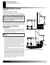
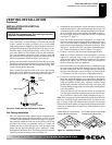
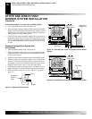
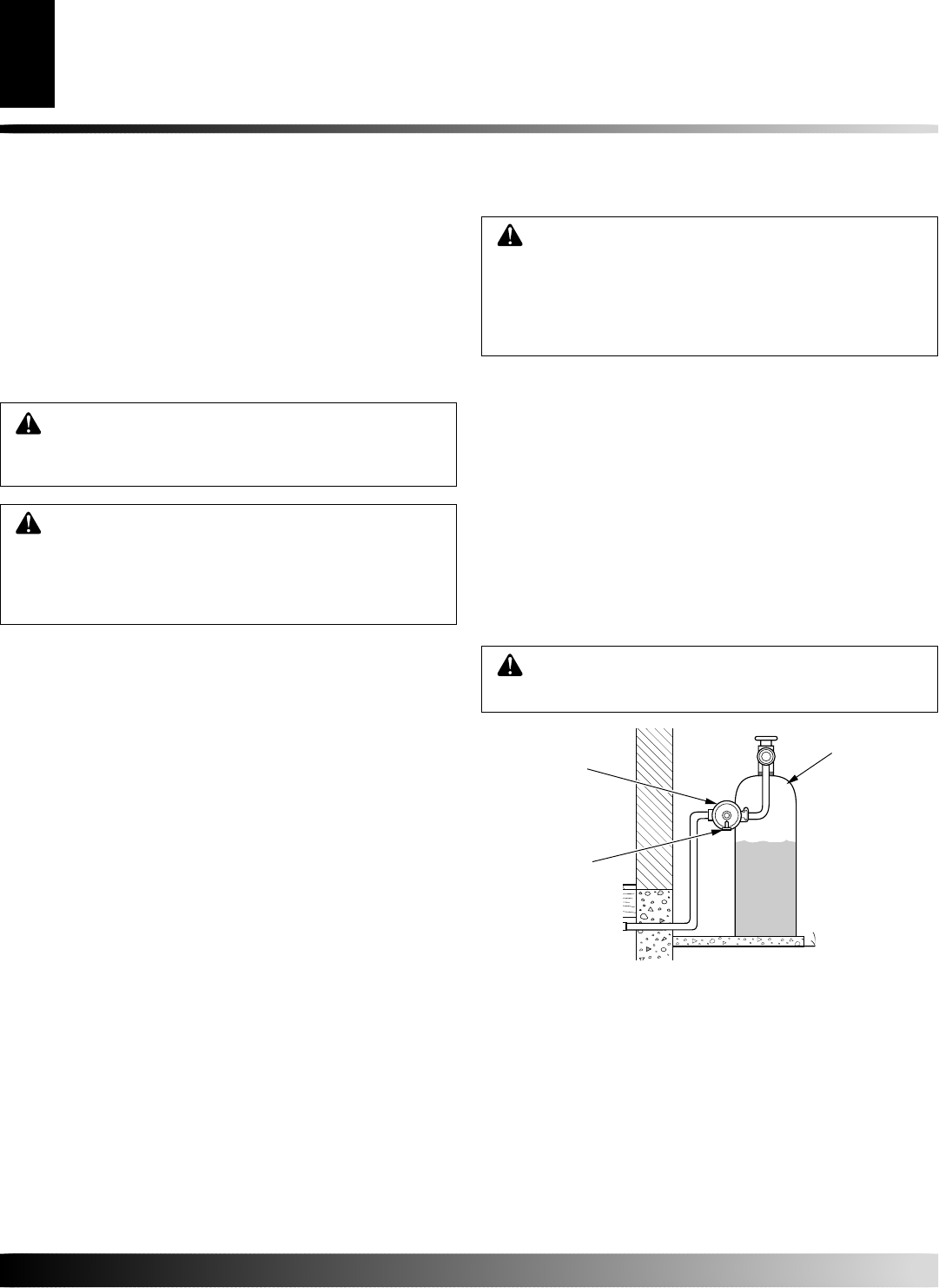
For propane/LP connections only, the installer must supply an
external regulator. The external regulator will reduce incoming gas
pressure. You must reduce incoming gas pressure to between 11 and
14 inches of water. If you do not reduce incoming gas pressure,
burner system regulator damage could occur. Install external regu-
lator with the vent pointing down as shown in Figure 38. Pointing
the vent down protects it from freezing rain or sleet.
WARNING: A qualified service person must con-
nect burner system to gas supply. Follow all local
codes.
CAUTION: For propane/LP units, never connect
burner system directly to the propane/LP supply.
This burner system requires an external regulator
(not supplied). Install the external regulator between
the burner system and propane/LP supply.
CHECK GAS TYPE
Use proper gas type for the burner system unit you are installing. If
you have conflicting gas types, do not install burner system. See
dealer where you purchased the stove and burner system for proper
burner system according to your gas type.
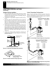
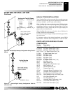
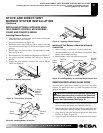
Installation must include an equipment shutoff valve, union, and
plugged 1/8" NPT tap. Locate NPT tap within reach for test gauge
hook up. NPT tap must be upstream from burner system (see Figure
39, page 19).
IMPORTANT:
Install equipment shutoff valve in an accessible
location. The main gas valve is for turning on and shutting off the
gas to the appliance.
Check your building codes for any special requirements for locating
equipment shutoff valve to stoves.
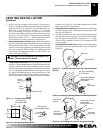
Apply pipe joint sealant lightly to male NPT threads. This will
prevent excess sealant from going into pipe. Excess sealant in pipe
could result in clogged burner system valves.
WARNING: Use pipe joint sealant that is resistant
to liquid petroleum (LP) gas.
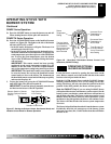
Figure 38 - External Regulator with Vent Pointing Down
(Propane/LP Only)
CAUTION: Use only new, black iron or steel pipe.
Internally-tinned copper tubing may be used in cer-
tain areas. Check your local codes. Use pipe of 1/2"
diameter or greater to allow proper gas volume to
burner system. If pipe is too small, undue loss of
volume will occur.
External
Regulator
Vent
Pointing
Down
Propane/LP
Supply Tank