


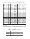

51
2) Circulator (Required) - Usually at least two circulators will be required to properly install a BWC Series boiler. See
the previous section for information on sizing the circulators.
3) Expansion Tank (Required) - If this boiler is replacing an existing boiler with no other changes in the system, the
old expansion tank can generally be reused. If the expansion tank must be replaced, consult the expansion tank
manufacturer’s literature for proper sizing.
4) Fill Valve (Required) - Either a manual or automatic fill valve may be used. The ideal location for the fill is at the
expansion tank.
5) Automatic Air Vent (Required) - At least one automatic air vent is required. Manual vents will usually be required
in other parts of the system to remove air during initial fill.
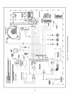
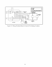
6) Manual Reset High Limit (Required by some codes) - This control is required by ASME CSD-1 and some other
codes. Install the high limit in the boiler supply piping just above the boiler with no intervening valves. Set the
manual reset high limit to 200°F. Wire the limit per Figures 10.1 & 10.2 in the Wiring section.
7) Flow Control Valve (Required) - The flow control valve prevents flow through the system unless the circulator is
operating. Flow control valves are used to prevent gravity circulation or “ghost flows” in circulator zone systems
through zones that are not calling for heat.
8) Isolation Valves (Recommended) - Isolation valves are useful when the boiler must be drained, as they will
eliminate having to drain and refill the entire system.
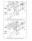
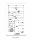
9) Drain Valve (Required) - The drain valve is installed on the return tee located in the lower vestibule compartment
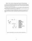
as shown in Figure 9.2.
10) Low Water Cut-off (Required) - The low water cut-off supplied with this boiler must not be removed.
D. Piping for Special Situations
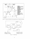
1) Systems containing oxygen - Many hydronic systems contain enough dissolved oxygen to cause severe corrosion
damage to an aluminum boiler such as the BWC. Some examples include:
• Radiant systems that employ tubing without an oxygen barrier.
• Systems with routine additions of fresh water.
• Systems which are open to the atmosphere.
If the boiler is to be used in such a system, it must be separated from the oxygenated water being heated with a
heat exchanger as shown in Figure 9.10. Consult the heat exchanger manufacturer for proper heat exchanger sizing
as well as flow and temperature requirements. All components on the oxygenated side of the heat exchanger, such
as the pump and expansion tank, must be designed for use in oxygenated water.
2) Piping with a Chiller - If the boiler is used in conjunction with a chiller, pipe the boiler and chiller in parallel as
shown in Figure 9.11. Use isolation valves to prevent chilled water from entering the boiler.
3) Air Handlers - Where the boiler is connected to air handlers through which refrigerated air passes, use flow control
valves in the boiler piping or other automatic means to prevent gravity circulation during the cooling cycle.
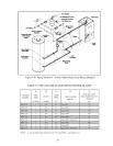
IMPORTANT
If there are any downturns, or downward pitches, in the boiler supply piping between the
boiler and the automatic air vent mounted on the system’s air separator, install a second
automatic air vent in the supply piping as close as possible to the boiler (Figures 9.2-9.4).
This will prevent nuisance low water cut-off lockouts due to trapped air.