


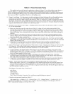

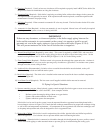
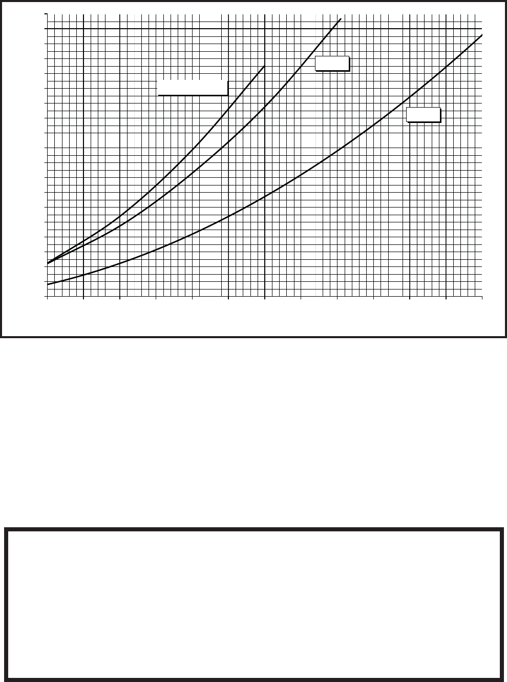
BWC070, BWC090
BWC120
BWC151
0.00
1.00
2.00
3.00
4.00
5.00
6.00
7.00
8.00
9.00
10.00
11.00
12.00
13.00
14.00
15.00
16.00
17.00
18.00
19.00
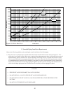
4 5 6 7 8 9 10 11 12 13 14 15 16
FLOW (GPM)
Head Loss (ft wc)
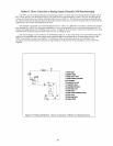
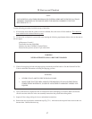
C: Standard Piping Installation Requirements
Observe the following guidelines when making the actual installation of the boiler piping:
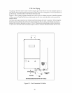
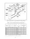
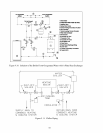
1) The relief valve is packaged loose with the boiler and must be installed in the location shown in Figure 2.1. The
relief valve is set to open at 30 psi. If the valve is replaced, the replacement must have a relief capacity in excess of
the DOE heating capacity for the boiler. Pipe the discharge of the relief valve to a location where water or steam
will not create a hazard or cause property damage if the valve opens. The end of the discharge pipe must terminate
in an unthreaded pipe. If the relief valve discharge is not piped to a drain, it must terminate at least 6 inches above
the floor. Do not run relief valve discharge piping through an area that is prone to freezing. The termination of the
relief valve discharge piping must be in an area where it is not likely to become plugged by debris.
50
Figure 9.9: Boiler Head Loss
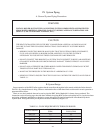
DANGER
PIPE RELIEF VALVE DISCHARGE TO A SAFE LOCATION.
DO NOT INSTALL A VALVE IN THE RELIEF VALVE DISCHARGE LINE.
DO NOT INSTALL RELIEF VALVE IN A LOCATION OTHER THAN THAT SPECIFIED BY THE
FACTORY.
DO NOT PLUG THE RELIEF VALVE DISCHARGE.