


VII Venting
WARNING
FAILURE TO VENT THIS BOILER IN ACCORDANCE WITH THESE INSTRUCTIONS COULD CAUSE
FLUE GAS TO ENTER THE BUILDING RESULTING IN SEVERE PROPERTY DAMAGE, PERSONAL
INJURY, OR DEATH:
* Use only vent systems and materials explicitly permitted by Crown for use with this boiler.
* Do not attempt to mix components from different approved vent systems.
* Do not obtain combustion air from within the building.
* Do not install a barometric damper or drafthood on this boiler.
A. Vent System Design
There are four basic ways to vent this boiler:
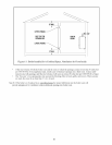
• Horizontal (“Side Wall”) Concentric Venting - Vent system exits the building through an outside wall.
Concentric venting consists of a “pipe within a pipe”. Flue gas exits the building through the inner pipe and
combustion air is drawn into the boiler through the space between the inner and outer pipe.
• Horizontal (“Side Wall”) Twin Pipe Venting - Vent system exits the building through an outside wall.
Combustion air and flue gas are routed between the boiler and outdoors using separate pipes.
• Vertical Concentric Venting - Vent system exits the building through the roof. Concentric venting consists of a
“pipe within a pipe”. Flue gas exits the building through the inner pipe and combustion air is drawn into the boiler
through the space between the inner and outer pipe.
• Vertical Twin Pipe Venting - Vent system exits the building through a roof. Combustion air and flue gas are
routed between the boiler and outdoors using separate pipes.
All of these systems are considered “direct vent” because in all of them air for combustion is drawn directly from
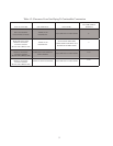
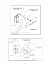
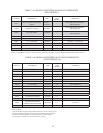
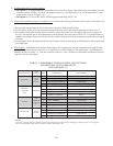
the outdoors into the boiler. A description of all of these venting options are shown in Tables 7.1 and 7.9. For clarity,
these vent options are numbered from 1 to 6. One of the vent option columns in Tables 7.1 or 7.9 must match the
planned vent and air intake system exactly. In addition, observe the following guidelines:
1) Approved vent systems - Use only one of the approved vent systems shown in Tables 7.4 or 7.5. These vent systems
fall into two basic categories:
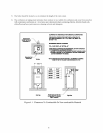
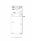
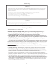
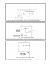
• Concentric Vent System - The standard boiler is supplied with a concentric vent system having a maximum
usable length of 25” (Figure 1.1). For longer runs, additional straight lengths and elbows are available from
Crown. In some cases, larger diameter concentric pipe must be used. Each Crown concentric vent component
consists of an inner pipe of polypropylene and the outer pipe of steel. Integral gaskets on each concentric fitting
provide a gas tight seal. A list of all Crown concentric vent components is shown in Table 7.4.
In this manual, concentric pipe sizes are called out in terms of the inner and outer pipe nominal diameters in
millimeters. For example, “60/100mm” pipe consists of a 60mm exhaust pipe inside a 100mm diameter outer pipe.
• Twin Pipe Vent Systems - Approved vent systems are made of a special stainless steel alloy (AL29-4C) for
protection against corrosive flue gas condensate. They are designed to provide a gas tight seal at all joints and
seams so that flue gas does not enter the building. Each approved vent system has a unique method for installation
- do not attempt to mix components from different vent systems. A list of approved twin pipe vent systems is
shown in Table 7.5. Note that a special vent collar (Crown PN 230510) is required if the boiler is to be vented
with one of the approved stainless vent systems.
11
CAUTION
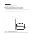
Moisture and ice may form on the surfaces around the vent termination. To prevent deterioration,
surfaces should be in good repair (sealed, painted, etc.).