


40
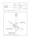
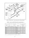
8) Installation of Vertical Exhaust Terminal - Use the terminal supplied by the vent system manufacturer shown in
Table 7.5. Attach to the vent system, following the assembly instructions in this manual for the stainless vent system
being used.
9) Assembly of the Air Intake System and Air Intake Terminals:
a) Assemble the air intake system using either galvanized or PVC pipe.
b) If PVC piping is used, use PVC cement to assemble the PVC intake system components.
c) If galvanized piping is used, use at least two sheet metal screws per joint. Seal the outside of all joints.
d) 3” galvanized smoke pipe will fit inside the inlet collar on the boiler. Depending upon the exact OD of the pipe
used, it may be necessary to crimp this pipe. Secure with a single #10 sheet metal screw through the hole in the
inlet collar and seal the outside of the joint with silicone. If PVC is used for the intake system, use a short piece
of 3” galvanized pipe to connect the PVC to the boiler. Silicone the outside of the joint between the PVC and
galvanized pipe.
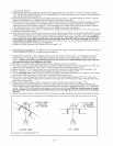
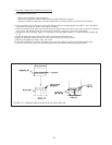
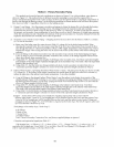
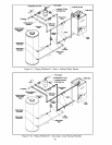
e) Horizontal intake terminal is a 90 degree elbow pointing down. Elbow should protrude the same distance from
the wall as the exhaust terminal.
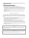
f) Vertical air intake terminal consists of a 180 degree bend (composed of two 90 degree elbows) as shown in
Figure 7.10.
g) Install a rodent screen (not supplied) in the inlet terminal. Use a screen having 1/2” (2 x 2) or larger mesh.
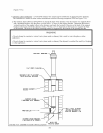
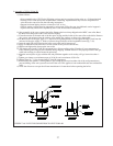
F. Condensate Trap and Drain Line
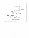
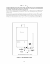
All condensate which forms in the boiler or vent system collects in the sump under the heat exchanger and
leaves the boiler through the condensate trap. This trap allows condensate to drain from the sump while retaining flue
gases in the boiler. The trap is supplied loose and must be installed as shown in Figure 7.51. A length of drain hose is
supplied with the boiler and is connected to the trap as shown in Figure 7.51. Note the following when disposing of the
condensate:
a) If the condensate drain line must be extended, construct the extension from PVC or CPVC pipe. Insert the hose
provided with the boiler into the end of the extension as shown in Figure 7.51.
b) Condensate is slightly acidic. Do not use metallic pipe or fittings in the condensate drain line. Do not route the
drain line through areas that could be damaged by leaking condensate.
c) Some jurisdictions may require that the condensate be neutralized before being disposed of. Dispose of
condensate in accordance with local codes.
d) Do not route, or terminate, the condensate drain line in areas subjected to freezing temperatures.
e) If the point of condensate disposal is above the trap, it will be necessary to use a condensate pump to move
the condensate to the drain. In such cases, select a condensate pump that is approved for use with condensing
furnaces. If overflow from this pump would result in property damage, select a pump with an overflow switch
and use this switch to shut down the boiler. Alternatively, if heat is a necessity, use the overflow switch to trigger
an alarm.
f) Do not attempt to move the trap from the location shown in Figure 7.51. Do not attempt to substitute another trap
for the one provided with the boiler.
g) The vent shown in Figure 7.51 must be left open for the trap to work properly.
CAUTION
BOILER CONDENSATE IS CORROSIVE. ROUTE CONDENSATE DRAIN LINE IN A MANNER SUCH
THAT ANY CONDENSATE LEAKAGE WILL NOT CAUSE PROPERTY DAMAGE.
WARNING
FAILURE TO INSTALL THE CONDENSATE TRAP AND CONDENSATE DRAIN IN ACCORDANCE WITH
THE ABOVE INSTRUCTIONS COULD CAUSE FLUE GAS TO ENTER THE BUILDING, RESULTING IN
PERSONAL INJURY OR DEATH.