


12
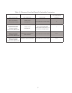
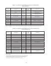
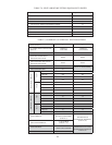
2) Maximum Vent and Air Intake Lengths - The maximum length of the vent air intake piping depends upon the vent
option selected and the boiler size. See Table 7.1 or 7.9 for the maximum vent length. In horizontal vent systems,
the lengths shown in Table 7.1 are in addition to the first standard elbow on top of the boiler. For vertical vent
systems, the maximum vertical vent lengths shown in Table 7.9 are in addition to two standard radius elbows. If more
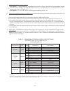
elbows are desired, the maximum allowable vent length must be reduced by the amount shown in Table 7.8 for each
additional elbow used. Termination fittings are never counted, although the length of the concentric terminal section
is counted.
Example:
A 60/100mm concentric vent system is planned for a horizontally vented BWC120 which has the following
components:
80/125 x 60/100mm Reducing Elbow (supplied with the boiler)
5ft Straight Pipe
90 elbow
1-1/2ft Straight Pipe
45Elbow
Uncut Terminal Section (supplied with the boiler)
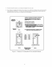
The Vent Option #1 column in Table 7.1 describes a horizontal direct vent system using 60/100mm concentric vent
pipe. From this column, we see that a BWC120 may have a vent length of up to 18ft. The 90 degree reducing elbow
is not considered. The length of the terminal section (not including the plastic terminal itself) is approximately 22
1/2” (1.9ft) installed. From Table 7.8, we see that the equivalent length of the 60/100mm elbow is 4.5ft and that the
equivalent length of the 45 degree elbow is 4ft. The total equivalent length of the planned venting system is therefore:
5ft (Straight ) + 4.5ft (90 Elbow) + 1.5ft (Straight ) + 4 ft (45 Elbow) + 1.9ft (Uncut Terminal Section) = 16.9ft.
Since Table 7.1 shows a maximum allowable vent length of 18ft, the planned vent system length is acceptable.
3) Minimum Vent and Air Intake Lengths - Observe the minimum vent lengths shown in tables 7.1 and 7.9.
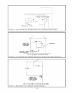
4) Permitted Terminals for Horizontal Venting:
• Vent Option 1 - The 60/100mm concentric vent terminal is supplied with the boiler as part of the standard vent
system.
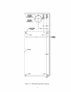
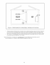
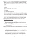
• Vent Option 2 - The exhaust terminal is Crown PN 230511. The air intake fitting is a 90 degree elbow with a rodent
screen supplied by the installer. This elbow is made out of the same material as the rest of the air inlet system
(either galvanized or PVC) and is installed as shown in Figure 7.3.
• Vent Option 3 - Two terminals are permitted:
a) 80/125mm Concentric Vent Terminal (Crown PN 230531)
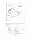
b) 80/125mm Snorkel Terminal (Crown PN 230540) . This terminal allows the vent system to exit the building
close to grade and go up the exterior wall far enough to provide adequate clearance between the terminal itself
and the snow line (Figure 7.7).
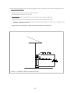
5) Horizontal Vent and Air Intake Terminal Location - Observe the following limitations on the vent terminal location
(also see Figures 7.6, 7.7). When locating a concentric terminal, observe the limitations outlined below for “vent
terminals”.
• Vent terminals must be at least 1 foot from any door, window, or gravity inlet into the building.
• For twin pipe terminals, maintain the correct clearance and orientation between the vent and air intake terminals.
The vent and air intake terminals must be at the same height and their center lines must be between 12 and 36
inches apart. Both terminals must be located on the same wall.
• The bottom of all terminals must be at least 12” above the normal snow line. In no case should they be less than
12” above grade level.
• The bottom of the vent terminal must be at least 7 feet above a public walkway.
• Do not install the vent terminal directly over windows or doors.
• The bottom of the vent terminal must be at least 3 feet above any forced air inlet located within 10 feet.
• USA Only: A clearance of at least 4 feet horizontally must be maintained between the vent terminal and gas
meters, electric meters, regulators, and relief equipment. Do not install vent terminal over this equipment. In
Canada, refer to B149.1 Installation Code for clearance to meters, regulators and relief equipment.
• Do not locate the vent terminal under decks or similar structures.
• Top of vent terminal must be at least 5 feet below eves, soffits, or overhangs. Maximum depth of overhang is 3 ft.