


22
C. Assembly of Crown 60/100mm Concentric Venting
(IMPORTANT - Skip to Section D for 80/125mm Concentric Vent Assembly)
WARNING
Failure to follow the instructions could result in flue gas leakage into the combustion air or indoor air,
resulting in unsafe or unreliable operation.
• Do not lubricate concentric gaskets with anything other than water.
• Do not attempt to cut any piping except as permitted in this section. When cutting these sections, make sure
all cuts are square and allow for proper insertion.
• Do not attempt to try to mix this concentric pipe with other venting systems.
1) Concentric vent components supplied with the boiler are packed inside the BWC070/090/120 carton and include
the following:
a) 80/125 x 60/100mm reducing elbow (Crown PN 230521).
b) 60/100mm terminal section (straight section with a terminal and overall length of 27 3/4” (Crown PN 230520).
c) Two (2) Rubber wall grommets (Crown PN 230522).
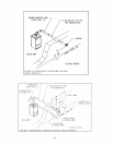
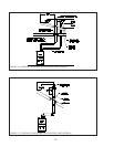
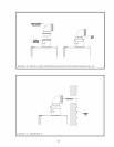
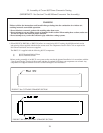
2) Unless the 80/125 straight riser (PN 230515) is used, start by attaching the reducing elbow to the boiler collar. To
do so, remove the clamp from the large end of the reducing elbow and set aside. Apply a small amount of water to
the brown gasket on the boiler collar. Push the elbow onto the boiler collar until the bead on the elbow contacts the
top edge of the collar (Figure 7.20).
3) Reinstall the clamp removed in Step (2) so that the elbow is secured to the boiler collar.
4) If no additional sections of concentric pipe are required, attach the terminal section to the elbow. In most cases, it
will need to be cut before doing so. Use the following procedure to cut the pipe:
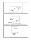
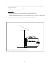
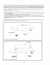
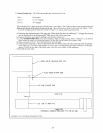
a) Measure distance “L” from the outside surface of the exterior wall to the end of the elbow as shown in Figure
7.21.
b) Add 2-1/8” to distance “L”. Carefully mark this length on the pipe as shown in Figure 7.22.
c) Press in the two tabs holding the plastic terminal in the terminal section (Figure 7.22). Carefully pull out the
terminal and the inner pipe.
d) Cut the outer pipe only at the point marked in Step (b) using aviation shears, a hacksaw, or an abrasive wheel
cutter. Be careful to cut the pipe square. De burr the cut end with a file or emery cloth.
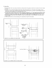
e) Cut the plastic inner pipe so that it will protrude 3/8” beyond the outer pipe when reinstalled in the terminal
section (Figure 7.23). Use a fine tooth hacksaw or a PVC saw to cut the plastic pipe and be careful to cut the pipe
square. De burr the cut edge of the plastic pipe with a file, razor blade, or fine sandpaper.
f) Reinstall the inner pipe in the terminal section. Slip the outside wall grommet over the terminal section and
position so that it covers the joint between the outer pipe and the terminal (Figure 7.24).
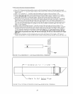
g) Make a mark on the terminal section 1” from the cut end of the outer pipe as shown in Figure 7.24.
h) Pass the terminal section through the wall from the outside. Push the remaining wall grommet over the terminal
section on the inside of the wall. Push the terminal section into the elbow until the mark made in Step (g) is no
longer visible. If necessary, the brown gasket in the inner pipe may be lubricated with a few drops of water.
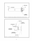
i) The terminal section must be attached to the elbow with a single #10 x 1/2” sheet metal screw ( not supplied) at
the top of the elbow. Drill a 1/8” hole in the location shown in Figure 7.25. Use a short drill bit or a drill stop
to ensure that the drill bit does not penetrate the pipe by more than 3/8”. Install a #10 x 1/2” screw in this
hole. Do not use a screw longer than 1/2” long.
j) If not already done, make sure that both wall grommets are firmly against the interior and exterior wall surfaces.
Seal any cracks or other openings near the terminal through which exhaust could enter the building.
5) If additional pieces of pipe are used, install them starting at the boiler elbow. Support each section of straight pipe
at its female end.