


37
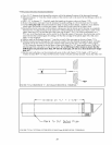
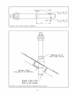
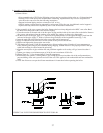
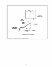
FIGURE 7.48: Z-VENT III CONNECTION TO VENT COLLAR
4) Assembly of Z-Flex Z-Vent III:
a) General Notes:
• Non-expanded ends of SVE Series III piping sections may be cut using aviation snips or a 24 thread per inch
hacksaw. File or sand the cut end smooth before assembling. Expanded ends may be cut to adapt the SVE
series III to the vent collar. See the following instructions.
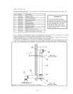
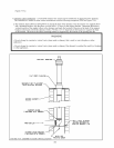
• Support horizontal piping sections at intervals of 48” or less.
• Vertical venting systems must be supported by at least one Z-Flex fire stop. An additional vertical support is
required after any offset and as required by the Z-Vent III installation instructions.
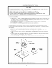
b) Start assembly of the vent system at the boiler. Remove the hose clamp shipped on the BWC vent collar. Bend
the three hose clamp tabs on this collar outward slightly.
c) Clean the exterior of the male end of the first piece of pipe and the inside of the vent collar on the boiler. Remove
dirt, grease, and moisture from the surfaces to be sealed. Dry surfaces or allow to dry thoroughly.
d) On the male end of the pipe, apply a ¼” wide bead of high temperature silicone approximately ½ inch from the
male end of the pipe. Apply ¼” beads of silicone along both sides of the longitudinal seam (Fig. 7.48).
e) Insert the male end of the pipe into the boiler vent collar until it bottoms out.
f) Apply an additional bead of silicone over the outside of the joint and smooth out.
g) Replace and tighten the clamp on the vent collar.
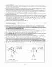
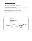
h) The female end of each Z-Vent III component has a silicone sealing gasket. Examine all vent components to
insure that the gasket integrity has remained during shipping. Gaskets must be in the proper position or flue gas
could leak resulting in carbon monoxide poisoning.
i) Align the second piece of pipe with the first and push them together as far as they will go, but not less than 1-
3/4”.
j) Tighten gear clamp to a minimum torque of 40 in-lbs and a maximum of 50 in-lbs.
k) Repeat Steps (h) – (j) for the remaining Z-Vent III components.
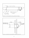
l) In horizontal vent systems, a locking band or gear clamp must be used at either side of the wall penetration to
prevent shifting of the vent system in and out of the wall. This applies to both combustible and non-combustible
walls.
n) Allow the silicone to cure per the silicone manufacturer’s instructions before operating the boiler.