


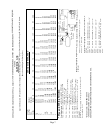
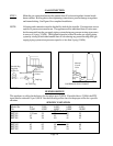

TABLE 1 – first stage pipe sizing
10 PSIG Inlet with a 1 PSIG Pressure Drop
Maximum capacity of pipe or tubing, in thousands of BTU/hr. of L.P. Gas
Size of Pipe LENGTH OF PIPE OR TUBING, FEET*
Or Copper
Tubing, Inches 10 20 30 40 50 60 70 80 90 100
3/8 558 383 309 265 235 213 196 182 171 161
Copper ½ 1387 870 700 599 531 481 443 412 386 365
Tubing 5/8 2360 1622 1303 1115 988 896 824 767 719 679
(O.D.) ¾ 3993 2475 2205 1887 1672 1515 1394 1297 1217 1149
½ 3339 2295 1843 1577 1398 1267 1165 1084 1017 961
Pipe ¾ 6982 4799 3854 3298 2923 2649 2437 2267 2127 2009
Size 1 13153 9040 7259 6213 5507 4989 4590 4270 4007 3785
1-1/4 27004 18560 14904 12756 11306 10244 9424 8767 8226 7770
1-1/2 40461 27809 22331 19113 16939 15348 14120 13136 12325 11642
2 77924 53556 43008 36809 32623 29559 27194 25299 23737 22422
125 150 175 200 225 250 275 300 350 400
3/8 142 130 118 111 104 90 89 89 82 76
Copper ½ 323 293 269 251 235 222 211 201 185 172
Tubing 5/8 601 546 502 467 438 414 393 375 345 321
(O.D.) ¾ 1018 923 843 790 740 700 664 634 584 543
½ 852 772 710 660 619 585 556 530 488 454
Pipe ¾ 1780 1613 1484 1381 1296 1224 1162 1109 1020 949
Size 1 3354 3039 2796 2601 2441 2305 2190 2089 1922 1788
1-1/4 6887 6240 5741 5340 5011 4733 4495 4289 3945 3670
1-1/2 10318 9349 8601 8002 7508 7092 6735 6426 5911 5499
2 19871 18005 16564 15410 14459 13658 12971 12375 11385 10591
*Total length of piping from outlet of first stage regulator to inlet of second stage regulator (or to inlet of second stage regulator furthest
away).
Notes: 1) To allow 2 PSIG pressure drop, multiply total gas demand by .707, and use capacities from table.
2) For different first stage pressures, multiply total gas demand by the following factors, and use capacities from table.
First State Pressure PSIG Multiply by
20 .844
21 .912 Data Calculated per NFPA #54 & 58.
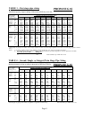
TABLE 4 – Second, Single, or Integral Twin Stage Pipe Sizing
11 Inches Water Column Inlet with a ½ Inch Water Column Drop
Maximum capacity of pipe or tubing in thousands of BTU/hr of LP-Gas
Size of Pipe LENGTH OF PIPE OR TUBING, FEET*
Or Copper
Tubing, Inches 10 20 30 40 50 60 70 80 90 100
3/8493427232019————
Copper 1/2 110 76 61 52 46 42 38 36 33 32
Tubing 5/8 206 141 114 97 86 78 71 67 62 59
(O.D.) 3/4 348 239 192 164 146 132 120 113 105 100
7/8 536 368 296 253 224 203 185 174 161 154
1/2 291 200 161 137 122 110 102 94 87 84
Pipe 3/4 608 418 336 287 255 231 212 198 185 175
Size 1 1146 788 632 541 480 435 400 372 349 330
1-1/4 2353 1617 1299 1111 985 892 821 764 717 677
1-1/2 3525 2423 1946 1665 1476 1337 1230 1144 1074 1014
2 6789 4666 3747 3207 2842 2575 2369 2204 2068 1954
125 150 175 200 225 250 275 300 350 400
3/8——————————
Copper 1/2 ——————————
Tubing 5/8 ——————————
(O.D.) 3/4 ——————————
7/8——————————
1/2 74 67 62 58 54 51 48 46 43 40
Pipe 3/4 155 141 129 120 113 107 101 97 89 83
Size 1 292 265 244 227 213 201 191 182 167 156
1-1/4 600 544 500 465 437 412 392 374 344 320
1-1/2 899 815 749 697 654 618 587 560 515 479
2 1731 1569 1443 1343 1260 1190 1130 1078 992 923
*Total length of piping from outlet of regulator to appliance furthest away. Data Calculated per NFPA #54 & 58.
Page 8
PROPANE GAS
PROPANE GAS