


3) Protect heater from wind, high traffic areas, and drafts (such as doorways, locations that get direct air from a ceiling
fan, etc.) as this will cause nuisance pilot outage.
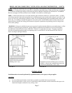
4) All models may be wall mounted using the factory supplied (standard) wall mounting bracket. Additionally all
models may be installed freestanding, by adding the optional VF-FSK Floor Stand Kit and using an approved, fire
resistant floor mat (available from factory). NOTE: Both wall and floor mount installations require hard piping.
5) If optional blower is to be added, locate heater so there is safe access to an electrical outlet.
INSTALLATION - CONTINUED
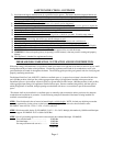
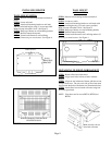
FIGURE 2
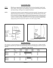
36”
6”
6”
3”
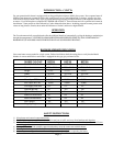
FIGURE 1
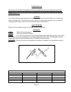
CLEARANCES
1) Maintain adequate accessibility clearances for
servicing and proper operation.
2) Minimum clearances as viewed from front of
heater, see Fig. 1. 3” clearance below heater
shall be measured from top surface of carpeting,
tile, etc.
3) If VF-FSK Free Standing Kit is used and the
heater is installed directly on carpeting, tile, or
other combustible material other than wood
flooring, the appliance shall be installed on a
metal or wood panel extending the full width
and depth of the appliance, such as a stove
board.
TOOLS AND ADDITIONAL SUPPLIES
REQUIRED
1) Pipe wrenches (2).
2) Phillip head screwdriver or screwgun.
3) Pressure test gauge.
4) An A.G.A. certified manual shut off valve
with 1/8” NPT pressure tap.
5) Union connector for type of piping used
(check local codes).
6) Pipe sealant certified for use with L.P. gas.
7) Components to assemble a drip leg.
8) Level.
9) Drill (if anchors are required).
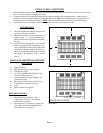
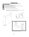
ROUGH-IN GAS SUPPLY
1) Determine location of heater. (See
“Operation”, “Fresh Air”, and “Safety
Instructions” for details.
2) Install at least a ½” diameter gas supply line.
(Gas supply can enter through bottom or
back of heater). See Figure 2.
Page 6
13-1/16”
1-5/8”
GAS INLET LOCATION