


BLOWER INSTRUCTIONS
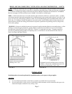
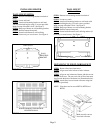
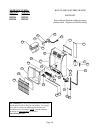
INSTALLING THE VFB BLOWER (BFT201 / BFT202, BFT301 / BFT302 MODELS ONLY)
STEP 1. Remove blower assembly from shipping carton.
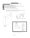
STEP 2. Insert blower assembly into upper back of heater (See Figure 11).
STEP 3. Secure blower to heater using three #8 screws (provided) through holes pre-punched in heater back.
STEP 4. Locate mounting holes for switchbox (See Figure 11).
STEP 5. Secure switchbox to heater using two #8 screws (provided).
STEP 6. Plug power cord into 115 volt three-prong grounded receptacle.
CAUTION: Always unplug power cord before servicing or cleaning heater.
Label all wires prior to disconnection when servicing controls. Wiring errors can cause improper
and dangerous operation. Verify proper operation after servicing.
FIGURE 11
Switchbox
Blower Assembly
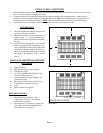
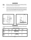
Blower
Motor
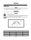
Black
White
Fan
Switch
White
(or ribbed)
Green
Black
WIRING DIAGRAM / VFB BLOWER
Page 14