


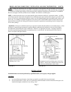
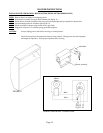

GAS CONNECTION
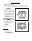
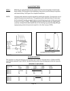
STEP 1. Make the gas connection between the manual shut off valve and regulator located inside
heater cabinet. Hold regulator when tightening connection to prevent damage to regulator
and internal tubing. See Figure 6 for completed installation.
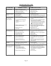
NOTE: All piping and connection must be checked for leaks by the installer. If connections are not
exposed, a pressure test must be run. The appliance and its individual shut off valve must
be disconnected from the gas supply piping system during any pressure testing at pressures
in excess of ½ psig (3.5 kPa). The appliance must be isolated from the gas supply piping
system by closing its individual manual shut off valve during any pressure testing of the gas
supply piping system at test pressures equal to or less than ½ psig (3.5kPa).
Internal Regulator
(Supplied)
Union
Drip Leg
Manual Shut Off
Outside Reg.
Supplied
by Gas Co.
1/8” NPT Plug
FIGURE 6
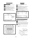
Manual
Cut off
Valve
1/8” NPT
Pressure
Plug
Drip
Leg
GAS PIPING WITH VF-FSK KIT
FIGURE 6A
Page 10
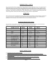
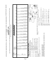
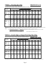
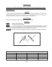
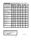
BURNER ORIFICE
This appliance is orificed at the factory for elevations up to 2,000 ft. If installed above 2,000 ft. the BTU
input must be reduced 4% per 1,000 ft. See the following orifice chart for the proper orifice for a specific
elevation.
SPECIFIC ELEVATION
Model No. 0 to 2,000 - 4,000 - 6,000 - 8,000 -
No. 2,000’ 4,000’ 6,000’ 8,000’ 10,000’
NATURAL GAS
BFT101 1.55 mm 54 54 55 55
BFT201 43 44 45 47 48
BFT301 36 38 40 41 43
L.P. GAS
BFT102 63 65 65 66 68
BFT202 55 55 56 56 57
BFT302 52 53 53 54 54