


7
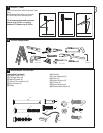
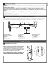
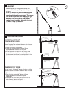
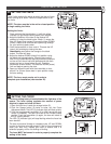
POSITION THE HEADER BRACKET
The header bracket must be rigidly fastened to a
structural support of the garage. Reinforce the wall or
ceiling with a 40mm (1-1/2") board if necessary.
Failure to comply may result in improper operation of
safety reverse system.
You can attach the header bracket either to the header
wall (1) or to the ceiling (3). Follow the instructions which
will work best for your particular requirements. With the
door closed, mark the vertical centerline (2) of the garage
door. Extend line onto header wall above the door.
Open door to highest point of travel. Draw an intersecting
horizontal line (4) on header wall 5 cm (2") above high
point to provide travel clearance for top edge of door.
Height depends on door type refer section 15.
3
1
2
4
12
13
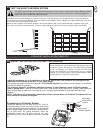
Wear protective goggles when working overhead to protect your eyes from injury.
Disengage all existing garage door locks to avoid damage to the garage door.
To avoid serious personal injury from entanglement, remove all ropes connected to the garage
door before installing the opener.
It is recommended that the opener be installed 2.1m (7 feet) or more above the floor where space permits.
INSTALLATION SECTION
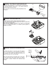
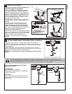
INSTALL THE HEADER BRACKET
UP
CEILING MOUNT ONLY
UP
CEILING MO
UNTONL
Y
2
1
50mm
(or 200mm)
3
5
5
B
UP
150mm
UP
CEILING MOUNT ONLY
5
1
2
3
A
4
DOOR
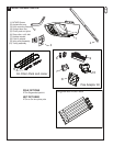
fig 1
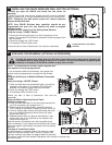
NOTE: Refer to vertical centre and horizontal lines
created in section 12 for proper placement of header
bracket.
A. Wall mount: centre the header bracket (1) on the
vertical centre line (2) with the bottom edge of the
header bracket on the horizontal line (the horizontal line
should be 50 mm for Sectional Doors & Tracked Tilt
Doors and 200mm for One Piece Tilt doors, above the
spring (4) (with the arrow pointing toward the ceiling).
Mark all of the header bracket holes (5). Drill 4.5mm
(3/16") pilot holes and fasten the header bracket with
wood screws (3).
B. Ceiling mount: extend vertical centre line (2) onto the
ceiling. Centre the header bracket (1) on the vertical
mark no more than 150mm (6") from the wall. Mark all
of the header bracket holes (5). Drill 4.5mm (3/16") pilot
holes and fasten the header bracket with wood screws
(3). For concrete ceiling mount, use concrete anchors
provided.
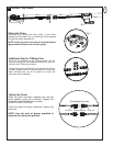
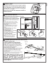
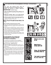
The Idler Pulley Bracket will also need to be turned
upside down (fig 1). To do this remove the chain from
the pulley, twist the Idler bracket 180
0
in to the upside
down position & reassemble the chain around the
pulley.