


16
4
2
3
1
WHT
-2
RED
-1
5
6
6mm
1
2
4
WHT
RED
1
4
LOCK
LIGHT
3
3
2
3
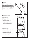
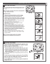
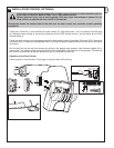
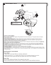
INSTALL DOOR CONTROL (OPTIONAL)
There are 2 terminals (1) on the back of the door control (2). Strip about 6mm (1/4") of insulation from bell wire
(4). Separate wires enough to connect the white/red wire to RED terminal screw 1 and the white wire to WHT
terminal screw 2.
Fasten the door control to an inside garage wall with sheet metal screws (3) provided. Drill 4mm (5/32") holes and
use anchors (6) if installing into plasterboard wall. A convenient place is beside the service door and out of reach
of children.
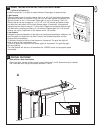
Run the bell wire up the wall and across the ceiling to the garage door operator. Use insulated staples (5) to
secure wire. The receiver quick connect terminals are located behind the light lens of the operator. Connect the
bell wire to the terminals as follows: white/red to red (1) and white to white (2).
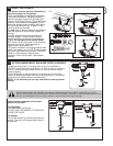
Operation of the Door Control
Press to open or close the door. Press again to stop the door while moving.
29
Locate door control where the garage door is visible, away from door and door hardware and out
of the reach of children. Mount at least 1.5m (5 feet) above the floor
Serious personal injury from a moving garage door may result from misuse of opener. Do not
allow children to operate the door control or transmitter.
Permanently fasten the caution label to the wall near the door control as a reminder of safe operating
procedures.