


10009459 7
Brookhaven Direct Vent Gas Fireplace
FP297A
INSTA VENT FREE
UVHB26 GAS SUPPLY
7/1/98
FP297A
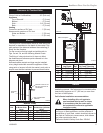
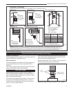
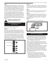
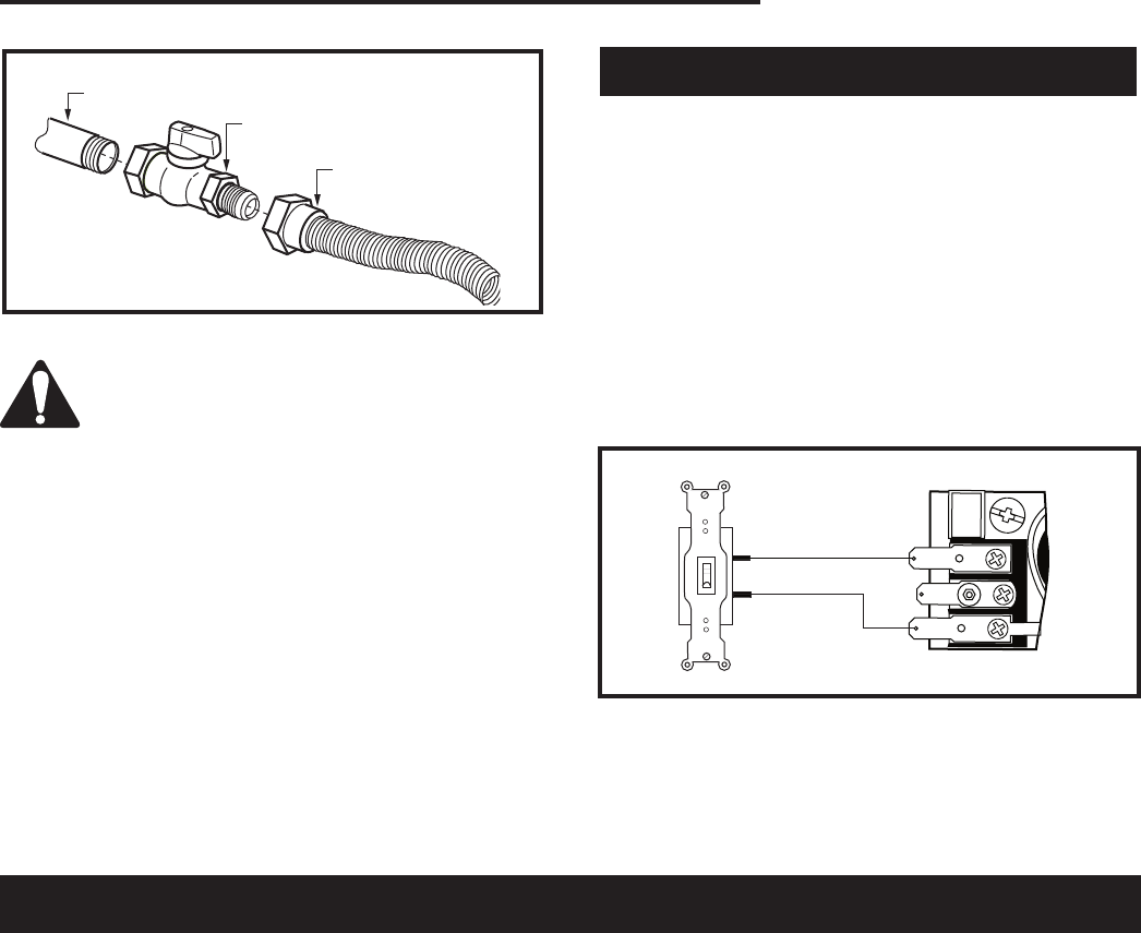
1/2” Gas Supply
1/2” NPT x 1/2” Flare Shut-
off Valve
3/8” Flex Line
(From Valve)
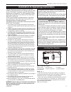
Fig. 5 Typical gas supply installation.
The fireplace valve must not be subjected
to any test pressures exceeding 1/2 psi.
Isolate or disconnect this or any other gas
appliance control form the gas line when
pressure testing.
The gas control is equipped with a captured screw type
pressure test point, therefore it is not necessary to pro-
vide a 1/8” test point up stream of the control.
When using copper or flex connector use only approved
fittings. Always provide a union when using black iron
pipe so the gas line can be easily disconnected for
burner or fan servicing. See gas specification for pres-
sure details and ratings.
The fireplace valve must not be subjected to any test
pressures exceeding 1/2 psi. Isolate or disconnect this
and any other gas appliance control from the gas line
when pressure testing.
Remote ON/OFF Switch
Do not wire the remote ON/OFF wall switch for this gas
appliance into a 120v power supply.
1. Thread wire through the electrical knockout located
on either side of the unit. Take care not to cut the
wire or insulation on metal edges. Ensure the wire is
secured and protected form possible damage. Run
one end of the gas control valve and the other end to
the conveniently located wall switch.
2. Attach the wire to the ON/OFF switch and install
switch into receptacle box. Attach cover plate to
switch.
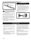
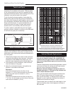
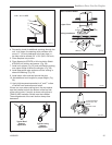
3. Connect wiring to gas valve. (Fig. 6)
TPTH
TH
TP
FP1218
Remote switch
wiring
8/02
Remote ON/OFF Switch
FP1218
Fig. 6 Remote switch wiring diagram for R models.
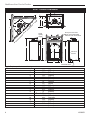
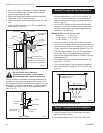
Your fireplace is approved to be vented either through
the side wall, or vertically through the roof.
• Only CFM Corporation venting components specifi-
cally approved and labelled for this fireplace may be
used.
• If vent termination is installed in an accessible loca-
tion, Vent Termination Guard #53525 shall be in-
stalled.
• Vent terminations shall not be recessed into a wall or
siding.
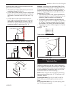
• Horizontal venting which incorporates the twist lock
pipe must be installed on a level plane without an
inclining or declining slope.
• Horizontal venting which incorporates the use of flex
venting shall have an inclining slope from the unit of
1/2” (13 mm) per 12” (305 mm).
General Venting
There must not be any obstruction such as bushes,
garden sheds, fences, decks or utility buildings within
24” (610 mm) from the front of the termination hood.
Do not locate termination hood where excessive snow
or ice build up may occur. Be sure to check vent termi-
nation area after snow falls, and clear to prevent ac-
cidental blockage of venting system. When using snow
blowers, make sure snow is not directed towards vent
termination area.
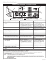
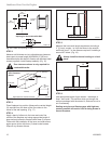
Location of Vent Termination
It is imperative the vent termination be located observ-
ing the minimum clearances as shown on the next
page.
*Check with local codes or in absence of same with
CSA B149.1 Installation Codes (1991) for Canada
or follow the current National Fuel Gas Code, ANSI
Z223.1/NFPA 54 for installations in the USA.