


10009459 11
Brookhaven Direct Vent Gas Fireplace
Horizontal plane means no vertical rise exists on this
portion of the vent assembly.
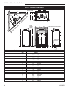
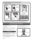
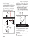
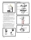
• The maximum number of 90° elbows per side wall
installation is three (3). (Fig. 11)
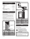
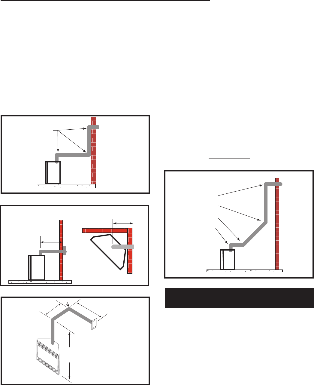
• If a 90° elbow is fitted directly on top of the fireplace
flange, the maximum horizontal vent run before the
termination or a vertical rise is 36” (914 mm). (Fig.
12)
• If a 90° elbow is used in the horizontal vent run
(level height maintained) the maximum horizontal
vent length is reduced by 36” (914 mm). (Fig. 12)
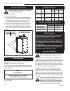
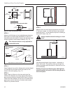
This does not apply if the 90° elbows are used to
increase or redirect a vertical rise. (Fig. 13)
3 x 90° Elbows
FP1176
Fig. 11 Maximum three (3) 90° elbows per installation.
Max 20"
Max 20"
36"
(914 mm)
Max.
36"
(914 mm)
Max.
FP1177
Fig. 12 Maximum horizontal run with no rise.
7'6"
(2.3m)
A
B
A + B = 17' (Max.)
(5.2m)
FP1178
Fig. 13 Horizontal run reduction.
Example: According to the vent graph (Page 10) the
maximum horizontal vent length in a system with a 7.5’
(2.3 m) vertical rise is 20’ (6 m) and if a 90° elbow is
required in the horizontal vent it must be reduced to 17’
(5.2 m). In Figure 13 Dimension A plus B must not be
greater than 17’ (5.2 m).
• The maximum number of 45° elbows permitted per
side wall installation is two (2). These elbows can be
installed in either the vertical or horizontal run.
• For each 45° elbow installed in the horizontal run,
the length of the horizontal run MUST be reduced by
18” (45 cm). This does not apply if the 45° elbows
are installed on the vertical part of the vent system.
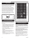
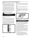
• The maximum number of elbow degrees in a system
is 270°. (Fig. 14)
Example:
Elbow 1 = 90°
Elbow 2 = 45°
Elbow 3 = 45°
Elbow 4 = 90°
Total angular variation = 270°
1
2
3
4
1
2
3
4
1 + 2 + 3 + 4 = 270°
FP1180
Fig. 14 Maximum elbow usage.
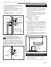
Vertical Sidewall Installation
Twist Lock Pipe
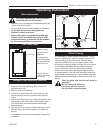
STEP 1
Locate vent opening on the wall. It may be necessary
to first position the fireplace and measure to obtain hole
location. Depending on whether the wall is combustible
or noncombustible, cut opening to size. (Fig. 15) (For
combustible walls first frame in opening.)
NOTE: When using flex vent, the opening will have to
be measured according to the 1/2” (13 mm) rise in 12”
(305 mm) vent run.
Combustible Walls
(Fig. 15): Cut a 9³⁄₈”H x 9³⁄₈” W
(240 x 240 mm) hole through the exterior wall and
frame.
Noncombustible Walls (Fig. 15): Hole opening must
be 7.5” (190 mm) in diameter.