


10009459 5
Brookhaven Direct Vent Gas Fireplace
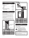
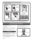
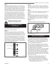
Top of Unit to Ceiling ................................32” (813 mm)
Front of Unit to Combustibles ...................36” (914 mm)
Appliance
Top of Standoff .........................................0” (0 mm)
Bottom ......................................................0” (0 mm)
Side .....................................................3/4” (19 mm)
Back .........................................................0” (0 mm)
Venting
Concentric sections of DV Vent ....................1” (25 mm)
Nonconcentric sections of DV Vent
Sides and Bottom ...................................1” (25 mm)
Top .........................................................2” (51 mm)
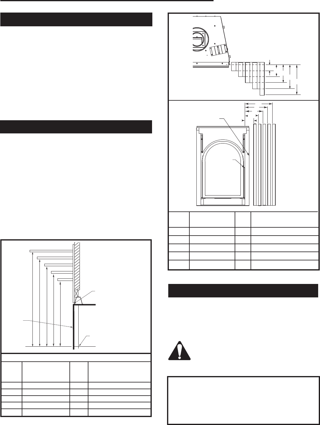
Clearance to Combustibles
Mantels
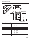
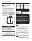
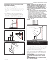
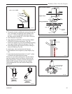
The height that a combustible mantel is fitted above the
fireplace is dependent on the depth of the mantel. This
also applies to the distance between the mantel leg (if
fitted) and the fireplace.
For the correct mounting height and widths refer to
Figs. 3a and 3b, and the following Mantel Charts.
The fitting of a bay window trim kit does not effect
the distances and reference points referred to in the
diagram and chart.
Noncombustible mantels and legs may be installed
at any height and width around the appliance. When
using paint or lacquer to finish the mantel, such paint or
lacquer must be heat resistant to prevent discoloration.
CFM170
J
F
G
H
I
CFM164b
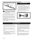
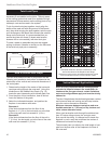
Mantel Leg Char
DVT44
4/9/03 djt
CFM170
DV Builder Front
View
O
N
M
L
K
Side of Fireplace
CFM164b
Mantel Mantel Leg From Side
Ref. Leg Depth Ref. of Comb. Opening
F 12 (305 mm) K 12” (305 mm)
G 9” (229 mm) L 9” (229 mm)
H 6” (152 mm) M 6” (152 mm)
I 4” (102 mm) N 4” (102 mm)
J 3” (76 mm) O 3” (76 mm)
Fig. 3b Combustible mantel leg minimum installation.
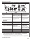
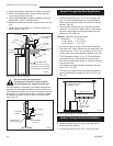
A hearth is not mandatory but is recommended for
aesthetic purposes. We recommend a noncombustible
hearth which projects out 12” (305 mm) or more from
the front of the fireplace.
Cold climate installation recommendation:
When installing this unit against a
non-insulated exterior wall or chase,
it is mandatory that the outer walls
be insulated to conform to applicable
insulation codes.
Hearth
Proposition 65 Warning: Fuels used in gas, wood-
burning or oil fired appliances, and the products of
combustion of such fuels, contain chemicals known to
the State of California to cause cancer, birth defects
and other reproductive harm.
California Health & Safety Code Sec. 25249.6
CFM146
A B C
D
E
V
W
X
Y
Z
Fireplace
CFM146
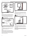
DV Mantel Chart
7/5/01 sta
Top of Combustion
Chamber
Mantel Chart
Fig. 3a Combustible mantel minimum installation.
Maintain minimum 2¹⁄₂”
(64 mm) clearance to
combustible
Mantel Shelf Mantel from Top of
Ref. or Breast Plate Ref. Combustion Chamber
Depth 20DVT
V 10” (254 mm) A 18
¹⁄₂” (470 mm)
W 8” (203 mm) B 16
¹⁄₂” (419 mm)
X 6” (152 mm) C 14¹⁄₂” (368 mm)
Y 4” (101 mm) D 12¹⁄₂” (318 mm)
Z 2” (51 mm) E 10
¹⁄₂” (267 mm)
Fireplace
Front
Combustion
Opening