


Brookhaven Direct Vent Gas Fireplace
6
10009459
Framing and Finishing
Check fireplace to make sure it is levelled
and properly positioned.
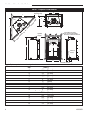
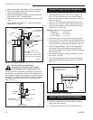
To mount the appliance:
1. Choose the location.
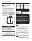
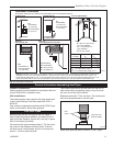
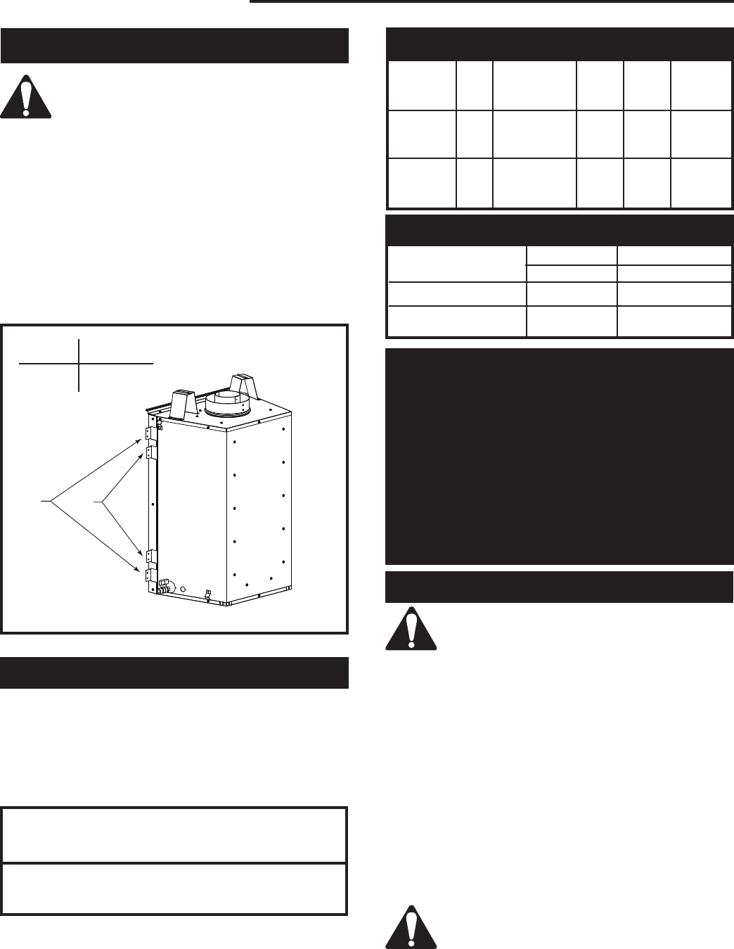
2. This unit comes with four (4) flanges pre-mounted
on both sides of the fireplace to allow two different
drywall thicknesses to be used. Flange “A” is for
1/2” drywall while flange “B” is for 5/8” drywall.
3. Bend the desired flanges out 90° on both sides of
the fireplace. Slide the fireplace into the framed
opening until the flanges contact the front surfaces
of the framing. Level the unit and secure it firmly in
place.
Fig. 4 Nailing flanges.
Flange Drywall
Position Depth
A 1/2” / 13 mm
B 5/8” / 16 mm
Flange Location for
Desired Drywall Depth
FP1539
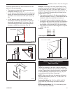
Noncombustible materials such as brick or tile may be
extended over the edges of the face of the fireplace.
DO NOT cover any vent or grille panels.
If a Trim Kit is going to be installed on the fireplace, the
brick or tile will have to be installed flush with the edges
of the fireplace.
Final Finishing
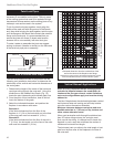
20DVT
Certified To
ANSI Z21.88-2005 / CSA 2.33-2005
Vented Gas Fireplace Heaters
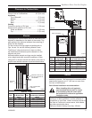
Inlet Minimum 5.5” w.c. 11.0” w.c.
Inlet Maximum 14.0” w.c. 14.0” w.c.
Manifold Pressure 3.5” w.c. 10.0” w.c.
Gas Inlet and Manifold Pressures
Natural LP (Propane)
High Elevations
Input ratings are shown in BTU per hour and are
certified without deration for elevations up to
4,500 feet (1,370m) above sea level.
For elevations above 4,500 feet (1,370m) in USA,
installations must be in accordance with the cur-
rent ANSI Z223.1/NFPA 54 and/or local codes hav-
ing jurisdiction.
In Canada, please consult provincial and/or local
authorities having jurisdiction for installations at
elevations above 4,500 feet (1,370m).
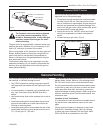
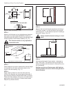
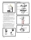
Gas Line Installation
When purging the gas lines, the front win-
dow frame assembly must be removed.
The gas pipeline can be brought in through the rear
of the appliance as well as the bottom. Knockouts are
provided on the bottom behind the valve to allow for the
gas pipe installation and testing of any gas connection.
It is most convenient to bring the gas line in from the
rear right side of the valve as this allows fan installation
or removal without disconnecting the gas line.
The gas line connection can be made with properly
tinned 3/8” copper tubing, 3/8” rigid pipe or an ap-
proved flex connector. Since some municipalities have
additional local codes, it is always best to consult your
local authority and the National Fuel Gas Code, ANSI
Z223.1/NFPA 54 in the USA or the CSA-B149.1 installa-
tion code.
Always check for gas leaks with a mild soap
and water solution applied with a brush no
larger than 1” (25 mm). Never apply soap
and water solution with a spray bottle. Do
not use an open flame for leak testing.
A
B
FP1626
flange location
5/06
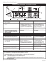
Unit: GFDN4B0
Max. Min. Air
Input Input Shutter
Model Fuel Gas Control BTU/h BTU/h Setting
Sides &
20DVTRN Nat. Millivolt Hi/Lo 13,000 8,700 Bottom
Half Open
Sides &
20DVTRP Prop. Millivolt Hi/Lo 13,000 8,700 Bottom
Half Open
Gas Specifications