


Brookhaven Direct Vent Gas Fireplace
14
10009459
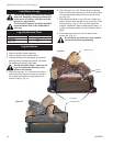
3. Install vent system. See Page 12, Steps 2 through 5.
4. Ensure a watertight seal is made around the vent
pipe coming through the wall.
5. Apply high temperature sealant caulking (supplied)
around the 4” and 7” snorkel collars.
6. Slide the snorkel into the vent pipe and secure to the
wall.
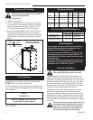
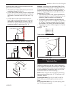
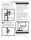
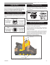
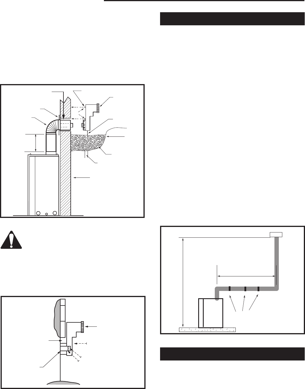
7. Level the soil to maintain a 4” (102 mm) clearance
below snorkel. (Fig. 21)
BG402a
Top Vent
Below grade installation
1/26/00 djt
Zero Clearance Sleeve
(if required)
Screws
7TDVSNORK
(Snorkel)
4” Clear-
ance Min.
Window
Well
Gravel
Drain
Foundation Wall
*A minimum of 24” (610 mm)
vertical pipe must be installed
when using the 7TDVSNORK.
Firestop
7” Pipe
24” (610 mm )
Minimum *
BG402a
Fig. 21 Below grade installation.
BG401
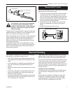
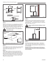
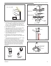
Snorkel
2/10/99 djt
Snorkel
Wall Screws
Sheet Metal
Screws
Foundation
Recess
Watertight Seal
Around Pipe
BG401
Fig. 22 Snorkel installation, recessed foundation.
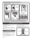
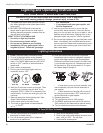
Vertical Through-the-Roof Application
This gas fireplace has been approved for:
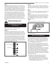
• Vertical installations up to 40’ (12 m) in height. Up
to a 10’ (3 m) horizontal vent run can be installed
within the vent system using a maximum of two 90°
elbows. (Fig. 23)
• Up to two 45° elbows may be used within the hori-
zontal run. For each 45° elbow used on the horizon-
tal plane, the maximum horizontal length must be
reduced by 18” (450 mm).
Example: Maximum horizontal length:
No elbows = 10’ (3 m)
1 x 45° elbow = 8.5’ (2.6 m)
2 x 45° elbows = 7’ (2.1 m)
• A minimum of an 8’ (2.5m) vertical rise is required.
• Two sets of 45° elbow offsets may be used within the
vertical sections. From 0 to a maximum of 8’ (2.5 m)
of vent pipe can be used between elbows. (Fig. 24)
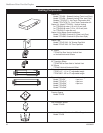
• 7DVCS supports offsets. (Fig. 25) This application
will require that you first determine the roof pitch
and use the appropriate starter kit. (Refer to Venting
Components List)
• The maximum angular variation allowed in the sys-
tem is 270°. (Fig. 24)
• The minimum height of the vent above the highest
point of penetration through the roof is 2’ (610 mm).
(Fig. 27)
Max. Height 40’ (12.2m)
Min. Height 8’ (2.4m)
Max. 10’ (3m)
Support Straps
Every 3’ (.9m)
FP1183
Fig. 23 Support straps for horizontal runs.
Vertical Through-the-Roof Installation
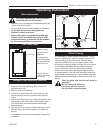
1. Locate your fireplace.
2. Plumb to center of the (4”) flue collar from ceiling
above and mark position.
3. Cut opening equal to 9
³⁄₈” x 9³⁄₈” (240 x 240 mm).
Do not backfill around snorkel.
A clearance of at lest 4” must be main
-
tained between the snorkel and the soil.
If the foundation is recessed, use recess brackets (not
supplied) for securing lower portion of the snorkel. Fas-
ten brackets to wall first, then secure to snorkel with self
drilling #8 x 1/2 sheet metal screws. It will be necessary
to extend vent pipes out as far as the protruding wall
face. (Fig. 22)