


9
Vermont Castings Intrepid Multi-Fuel
2000970
Floor Protection
Specifications herein are primarily for common timber
frame construction.
The floor beneath the stove requires protection from
radiant heat and direct contact with sparks or embers.
Heat protection is provided by a Vermont Castings Bot-
tom Heat Shield, part #0307.
Spark and ember protection is provided by a floor
protector, which may be any noncombustible material.
Consult your local building code for floor protection size
and composition. Figure 9 indicates specifications for
the U.S. and Canada.
For new hearth construction specifications and require-
ments, refer to your local building codes.
When using brick, tile, or stone, individual pieces must
be mortared so sparks cannot fall through.
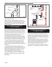
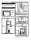
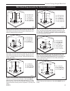
Floor protection also must extend under the chimney
connector and 2” to either side (‘C’, Fig. 10) For 6”
(150mm) connector used with the Intrepid Multi-Fuel,
the protector must be a minimum of 10” (250mm) wide,
centered under the connector.
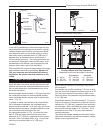
hearths can be a fire hazard and are considered a com
-
bustible floor.
Keep in mind that many raised hearths will extend less
than the required clearance from the front of the heater
when it is installed. In such cases, sufficient floor
protection as described above must be added in front
of the hearth to satisfy the minimum floor protector re-
quirement from the front of the stove. Fireplace hearths
must also offer the required protection of 6” (152 mm)
on either side.
Optional 3” (75 mm) short legs may be used only on
such hearths that meet the width and depth require-
ments outlined previously under “floor protection.”
Hearth rugs do not satisfy the requirements for floor
protection.
Fireplace installations also have special clearance
requirements to the side walls, side decorative trim, and
fireplace mantel. Refer to the information on fireplace
and mantel trim shields in this section.
D
E
D
D
A
B
D
D
A
E
D
C
ST500
intrepid
floor protection
11/10/00
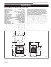
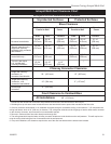
Top Exit Rear Exit
A. 34” 38” (965 mm)
B. 40” 44” (1118 mm)
C. 10” 10” (254 mm)
D. 6” 6” (152 mm)
E. 16” 18” (457 mm)
U.S. Canada
ST500
Fig. 10 Required floor protector dimensions.
Floor Protection for Fireplace Installations
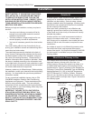
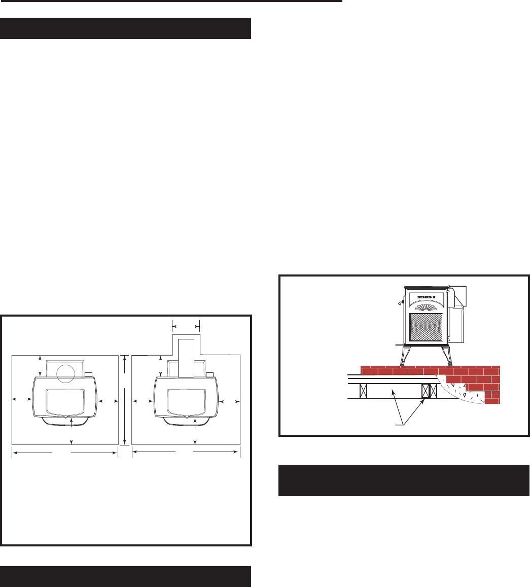
Do not assume your fireplace hearth is completely
noncombustible.
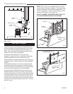
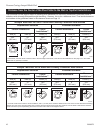
Many fireplace hearths do not satisfy the “completely
noncombustible” requirement because the brick or
concrete in front of the fireplace opening is supported
by heavy wood framing as in Figure 11. Because heat
passes through brick or concrete readily, it can easily
pass through to the wood. As a result, such fireplace
ST247
Rear exit floor dgrm
12/14/99 djt
Wood framing requires pro-
tection form radiant heat
ST247a
Fig. 11 Supporting timbers under fireplace hearth are consid-
ered to be combustible.
Keep the Stove and Connector a Safe Dis-
tance from Surrounding Materials
Specifications herein are primarily related to common
timberframe construction. Both a stove and its chimney
connector radiate heat in all directions when operat-
ing, and dangerous overheating of nearby combustible
materials can occur if they are too close to the heat. A
safe installation requires that adequate clearance be
maintained between the hot stove and its connector
and nearby combustibles.
Clearance is the distance between either your stove
(measured from the back edge of the stove’s top plate)
or chimney connector, and nearby walls, floors, the
ceiling, and any other fixed combustible surface. Your
stove has special clearance requirements that have
been established after careful research and testing.
These clearance requirements must be strictly ob-
served.