


15
Vermont Castings Intrepid Multi-Fuel
2000970
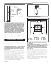
Wall Shield Requirements for Common Installations
C
C
C
C
D
F
A
B
E
D
ST508
Intrepid II
wall shield
11/00
I
N
T
R
E
P
I
D
I
I
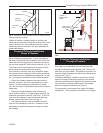
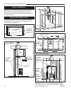
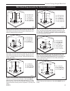
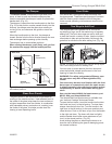
A = 36” (914 mm)
B = 30” (762 mm)
C = 1” (25 mm)
D = 35” (889 mm)
E = 44” (1118 mm)
F = 40” (1016 mm)
ST508c
Fig. 23 Parallel installation, vertical chimney connector, with
stove, connector and wall shields. Maximum reduction for rear
and side walls. Wall shields may meet at corner. A heat shield
24” (610 mm) in diameter suspended 1” (25 mm) below the ceil-
ing must surround the chimney.
B
B
A
D
A
C
C
A
D
A
ST510
Wall shield
cc
11/00
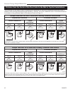
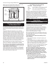
A = 1” (25 mm)
B = 34” (864 mm)
C = 48” (1219 mm)
D = 35” (889 mm)
ST510c
Fig. 25 Corner installation, vertical chimney connector, two wall
shields. Reduced side clearances. Wall shields MUST meet at
corner.
IN
T
R
E
PI
D
II
C
C
C
C
D
F
A
B
E
D
ST508
Intrepid II
wall shield
11/00
I
N
T
R
E
P
I
D
I
I
ST508b
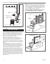
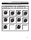
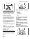
Fig. 20 Parallel installation, vertical chimney connector, two
wall shields. Reduced clearances for both rear and side walls.
Wall shields may meet at corner if desired. Shielding for con-
nector is centered behind connector.
A = 36” (914 mm)
B = 30” (762 mm)
C = 1” (25 mm)
D = 35” (889 mm)
E = 44” (1118 mm)
F = 40” (1016 mm)
B
B
A
D
A
C
C
A
D
A
ST510
Wall shield
cc
11/00
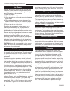
A = 1” (25 mm)
B = 34” (864 mm)
C = 48” (1219 mm)
D = 35” (889 mm)
ST510b
Fig. 22 Corner installation, vertical chimney connector, with
rear, stove, connector and wall shields. Wall shields MUST
meet at corner. Connector heat shield extends 28” (711 mm)
above flue collar. A 24” (610 mm) diameter ceiling heat shield
must surround the chimney and be suspended 1” (25 mm) from
ceiling.
B
C
D
C
E
A
D
ST509a
Wall shield
BB
11/00
I
N
T
R
E
P
I
D
I
I
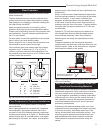
A = 36” (914 mm)
B = 13” (330 mm)
C = 35” (889 mm)
D = 1” (25 mm)
E = 40” (1016 mm)
ST509b
Fig. 21 Parallel installations with rear wall pass-through, two
wall shields. Reduced clearances for both rear and side walls.
Wall shields may meet at corner if desired. Shielding for con-
nector is centered behind connector. Wall pass-through must
comply with codes.
B
F
G
C
D
C
E
A
D
ST509
Wall shield
BB
11/00
I
N
T
R
E
P
I
D
I
I
A = 36” (914 mm)
B = 13” (330 mm)
C = 35” (889 mm)
D = 1” (25 mm)
E = 40” (1016 mm)
F = 30” (762 mm)
G = 44” (1118 mm)
ST509c
Fig. 24 Parallel installation with rear wall pass-through, with
stove, connector and wall shields. Wall shields may meet at
corner. Connector heat shield extends 28” (711 mm) above flue
collar, or below elbow, whichever is less. Wall pass-through
must comply with codes.