


6
Vermont Castings Intrepid Multi-Fuel
2000970
Double-wall Chimney Connector
Information on assembling and installing double-wall
connector is provided by the manufacturer of the dou-
ble-wall pipe. Follow the manufacturer’s instructions
exactly as you assemble the connector and attach it to
the stove and chimney. Using connectors and chim-
neys from the same manufacturer makes the assembly
and installation straightforward.
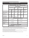
NOTE: For installations using double-wall con-
nectors, minimum clearances must conform to the
listed clearances in the clearance chart on Page 13.
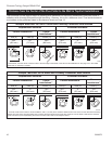
Single-wall Chimney Connector
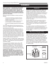
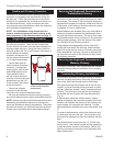
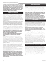
• Beginning at the flue collar of the stove, assemble
the chimney connector. Insert the first crimped end
into the stove’s flue collar, and keep each crimped end
pointing toward the stove. Using the holes in the flue
collar as guides, drill 1/8” (3 mm) holes in the bottom of
the first section of chimney
connector and secure it to
the flue collar with three #10
x 1/2” sheet metal screws.
• Secure each joint be
-
tween sections of chimney
connector, including tele-
scoping joints, with at least
three sheet metal screws.
The predrilled holes in
the top of each section of
chimney connector serve as
guides when you drill 1/8”
(3 mm) holes in the bottom
of the next section.
• Secure the chimney
connector to the chimney.
Instructions for various installations follow.
• Be sure the installed stove and chimney connector
are correct distances from nearby combustible material.
NOTE: Special slip pipes and thimble sleeves that form
telescoping joints between sections of chimney con-
nector are available to simplify installations. They often
eliminate the need to cut individual connector sections.
Consult your local dealer about these special pieces.
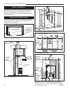
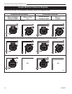
Securing the Single-wall Connector to a
Prefabricated Chimney
For prefabricated chimneys, follow the installation
instructions of the chimney maker exactly as you install
the chimney. The maker of the chimney will supply the
accessories to support the chimney, either from the roof
of the house, at the ceiling of the room where the stove
is installed, or from an exterior wall.
Special adaptors are available from your local dealer to
make the connection between the prefabricated chim-
ney and the chimney connector. The top of such adap-
tors attaches directly to the chimney or to the chimney’s
ceiling support package, while the bottom of the adap-
tor is screwed to the chimney connector.
These adaptors are designed so the top end will fit
outside the inner wall of the chimney, and the bottom
end will fit inside the first section of chimney connector.
When assembled in this way, any soot or creosote fall
-
ing from the inner walls of the chimney will stay inside
the chimney connector.
Securing the Single-wall Connector to a
Masonry Chimney
For masonry chimneys, both freestanding and fireplace
chimneys may be used for installation of your Intrepid
Multi-fuel.
Freestanding Chimney Installations
If the chimney connector must pass through a combus-
tible wall to reach the chimney, follow the recommenda-
tions in the Wall Pass-through section that follows.
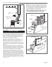
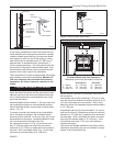
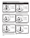
The opening through the chimney wall to the flue (the
“breach”) must be lined with either a ceramic or metal
cylinder, called the “thimble”, which is cemented firmly
in place. The fit must be snug and the joint between
the thimble and the chimney wall must be cemented.
(Fig. 6)
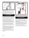
A special piece called the “thimble sleeve,” slightly
smaller in diameter than standard connector and most
thimbles, will facilitate the removal of the chimney con-
nector system for inspection and cleaning. Thimble
sleeves should be available from your local dealer. (Fig.
5)
To install a thimble sleeve, slide it into the breach until
it is flush with the inner flue wall. Do not extend it into
the actual flue passage, as this could interfere with the
draft.
The thimble sleeve should protrude 1-2” (25-50 mm)
into the room. Use furnace cement and thin gasketing
to seal the sleeve in place in the thimble. Secure the
chimney connector to the outer end of the sleeve with
sheet metal screws.
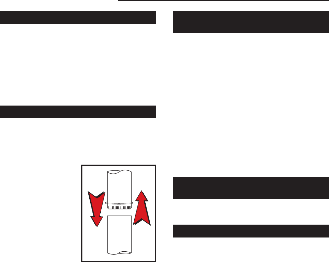
ST242
Chimney connector
12/13/99 djt
Fig. 4 The crimped end
of the connector points
toward stove.