


10
Vermont Castings Intrepid Multi-Fuel
2000970
In addition, furnishings and other combustible materials
must be kept away from the stove as well. In general, a
distance of 48” (1220 mm) must be maintained between
the stove and moveable combustible items such as dry-
ing clothes, furniture, newspapers, firewood, etc. Keep-
ing those clearance areas empty assures that nearby
surfaces and objects will not overheat.
Reducing Clearances
Stove clearances may be reduced by using heat shields
attached to the stove. Chimney connector clearances
may be reduced by using heat shields on single-wall
connector, or by using double-wall connector. Clear-
ances may also be reduced by using wall shields. All
shielding used to reduce clearances must be listed by a
recognized testing laboratory and approved by the local
regulatory body.
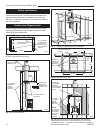
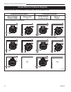
Clearance requirements are established for many differ
-
ent installations. In general, the greatest clearance is
required when you are placing a stove and its connec-
tor with no heat shields near a wall with no heat shield.
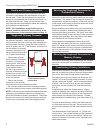
For example, when the Intrepid Multi-Fuel is installed
parallel to the rear wall and no shielding is used, it must
be at least 30” (760 mm) from the wall behind it and at
least 24” (610 mm) from walls on either side.
If the Intrepid Multi-Fuel is installed in a corner and no
shields are used, the corners of the stove must be at
least 20” (510 mm) from nearby walls.
The least clearance is required when both the stove
and its connector, as well as the wall, have heat
shields.
When shields are attached to the stove or chimney
connector, they are mounted 1” - 2” (25-50mm) away
from the stove or connector surface on noncombustible
spacers. Air flowing between the stove (and/or chimney
connector) and nearby shields carries heat away. Do
not block the air flow by filling this empty space with any
insulating material.
The shiny surface facing the heat source must be left
unpainted, enabling heat to reflect back towards the
stove or connector and away from the wall. Shields are
never used on double-wall connectors.
Clearances may be reduced only by means approved
by the regulatory authority, and in accordance with the
clearances listed in this manual.
Because of their restricted air flow and heat retention
characteristics, specific construction requirements and
special clearances apply to installations into alcoves.
Refer to the diagrams on Page 12, and contact your
Vermont Castings dealer for details before beginning an
alcove installation.
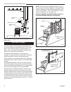
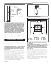
Stove Heat Shields
The Vermont Castings Intrepid Multi-Fuel Rear Heat
Shield is one way to reduce the clearance to the rear
wall. The rear heat shield may be installed on either
rear- or top-exiting stoves. However, since the chimney
connector also radiates heat toward the wall in top-exit-
ing installations, either single-wall connector with con-
nector heat shields, or listed and approved double-wall
chimney connector should be used whenever the rear
heat shield is used on top-exiting stoves.
Clearance reductions with the rear heat shield apply
only to the wall to the rear in parallel installations. Nei-
ther the side clearance requirement nor the clearance
requirement in corner installations may be reduced.
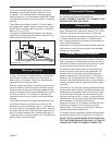
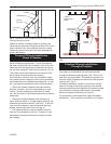
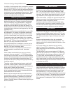
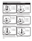
Wall Shields
Clearances may be reduced by using a wall shield
constructed of 24 gauge or heavier sheet metal, or of
another noncombustible material such as 1/2” (13 mm)
insulation board or common brick “laid on flat,” with the
3¹⁄₂" (90 mm) side down. Figure 12 shows such a wall
shield.
Shields must be spaced out from the combustible
surface 1" (25 mm) on noncombustible spacers. The
spacers should not be directly behind the stove or chim-
ney connector.
Air must be able to flow between the wall and the
shield. At least 50% of the bottom 1" (25 mm) of the
shield should be open and the shield must be open at
the top. (Fig. 12)
The wall shield for a stove must extend 10” (250 mm)
above the top of the stove, or a height of 35” (890 mm).
The wall shield for the chimney connector must be 28”
(710 mm) wide, centered behind the connector; for
installations that use an approved prefabricated chim-
ney to pass through the ceiling, the chimney connector
shield used with single-wall connector must stop 1” (25
mm) below the ceiling.
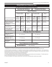
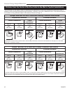
Chimney Connector Clearance Reductions
Chimney connector clearances may be reduced by
using heat shields on single-wall connector or by using
double-wall connector. One of these methods should
be used whenever the rear heat shield is used in top-
exit installations, or in any other situation when it is
necessary to protect nearby combustibles from the heat
of the chimney connector. The ceiling above horizontal
runs of chimney connector must be protected as well
if the clearance is inadequate. Refer to the Clearance
Charts.