


8
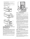
Step 3 — Locate Unit — The following guidelines
should be considered when choosing a location for a WSHP:
• Units are for indoor use only.
• Locate in areas where ambient temperatures are between
39 F and 102 F and relative humidity is no greater than
75%.
• Provide sufficient space for water, electrical and duct
connections.
• Locate unit in an area that allows easy access and removal
of filter and access panels.
• Allow enough space for service personnel to perform
maintenance.
• Return air must be able to freely enter the space if unit needs
to be installed in a confined area such as a closet.
• Install the unit on a piece of rubber, neoprene or other
mounting pad material for sound isolation. The pad
should be at least
3
/
8
in. [10 mm] to
1
/
2
in. [13 mm] in
thickness. Extend the pad beyond all four edges of the
unit.
• Provide adequate clearance for filter replacement and
drain pan cleaning. Do not block filter access with pip-
ing, conduit or other materials. Refer to Fig. 1, 3, and 4
for dimensional data.
• Provide access for fan and fan motor maintenance and
for servicing the compressor and coils without removing
the unit.
• Provide an unobstructed path to the unit within the closet
or mechanical room. Space should be sufficient to allow
removal of the unit, if necessary.
• In limited side access installations, pre-removal of the
control box side mounting screws will allow control box
removal for future servicing.
• Provide access to water valves and fittings and screw-
driver access to the unit side panels, discharge collar and
all electrical connections.
NOTE: Correct placement of the horizontal unit can play an
important part in minimizing sound problems. Since duct-
work is normally applied to these units, the unit can be
placed so that the principal sound emission is outside the oc-
cupied space in sound-critical applications. A fire damper
may be required by the local code if a fire wall is penetrated.
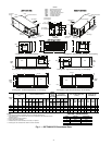
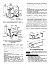
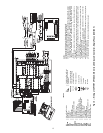
FIELD CONVERSION OF DISCHARGE AIR — The dis-
charge air of the 50PTH horizontal units can be converted
between side and back discharge in the field. The conversion
process is the same for right and left return configurations. See
Fig. 7 and 8.
NOTE: It is not possible to convert return air between left or
right return models in the field due to refrigerant piping
changes.
Preparation
— The unit should be on the ground in a well lit
area. Hung units should be taken down to ground level before
converting.
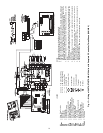
Side to Back Discharge Conversion
1. Remove screws to free the top and discharge panels. Set
screws aside for later use. See Fig. 8.
2. Remove the access panel and set aside.
3. Lift the discharge panel from side of unit and rotate it to
back using care not to damage blower wiring.
4. Check blower wire routing and connections for undue
tension or contact with sheet metal edges. Re-route if
necessary.
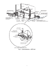
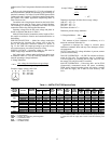
Return
Air
Power
Thermostat
Wiring
Compressor
Access Panel
Balancing Valve
(field-installed
accessory)
Low Pressure
Drop Water
Control Valve
(optional)
(field-installed
accessory)
Ball Valve with optional
integral P/T plug
(typical for supply and
return piping) (field-Installed
accessory)
Water
Out
Water
In
Building
Loop
Supply Air
Flexible
Connection
Stainless steel
braid hose
with integral
“J” swivel
(field-installed
accessory)
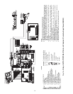
Return
Air
Power
Thermostat
Wiring
Compressor
Access Panel
Balancing Valve
(field-installed
accessory)
Low Pressure
Drop Water
Control Valve
(optional)
(field-installed
accessory)
Ball Valve with
optional integral
P/T plug (typical for
supply and return
piping)(field-installed
accessory)
Water
Out
Water
In
Building
Loop
Supply Air
Flexible
Connection
Flexible
Connection
Stainless
steel
braid hose
with
integral ”J”
swivel(field-
installed
accessory)
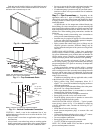
NOTE: Ball valve with integral pressure temperature plug recommended.
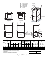
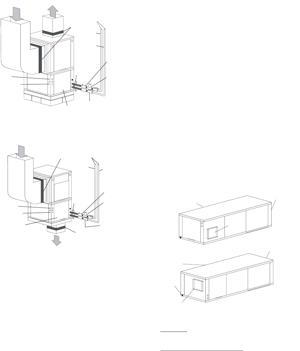
Fig. 5 — Typical Vertical Installation — 50PTV Unit
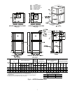
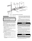
NOTE: Ball valve with integral pressure temperature plug recommended.
Fig. 6 — Typical Downflow Installation —
50PTD Unit
Water
Connection End
Supply
Duct
Return Air
Water
Connection End
Drain
Return Air
Discharge Air
Side Discharge
Back Discharge
Fig. 7 — Conversion Right Return,
Side Discharge to Back Discharge