


14
ECM
Y
GGGGR
W
O
Y
2
Y
1
G
R
C
Y
2
Y
1
G
O
W
C
R
D
H
A
L
1
A
A
A
L
1
S
W1
S
W2
S
W3
S
W4
S
W5
S
W6
S
W7
S
W8
S
W9
OF
F
ON
G
D
E
HUM
C
F
M
T
B
1
J1
S
1
BM ECM
ECM
INTERFACE
BOARD
S
W
1
S
W
2
S
W
3
S
W
4
S
W
5
S
W
6
S
W
7
S
W
8
S
W
9
OF
F
ON
S
1
J1
BM ECM
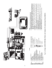
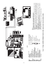
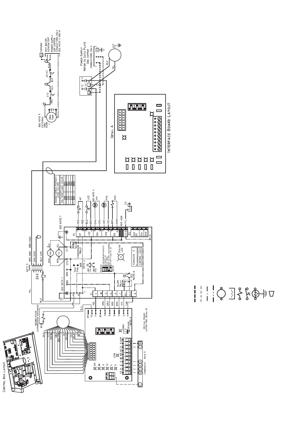
AL — Alarm Relay Contacts
ASTAT — Aquastat
BM — Blower Motor
BR — Blower Relay
CB — Circuit Breaker
CC — Compressor Contactor
CO — Sensor, Condensate Overflow
DTS — Discharge Temp Switch
ECM — Electronically Commutated Motor
FP1 — Sensor, Water Coil Freeze Protection
FP2 — Sensor, Air Coil Freeze Protection
HP — High-Pressure Switch
HWG — Hot Water Generator
JW1 — Jumper, Alarm
LOC — Loss of Charge Pressure Switch
MV — Motorized Valve
NEC — National Electrical Code
P1 — Field Wiring Terminal Block
RVS — Reversing Valve Solenoid
TRANS — Transformer
NOTES:
1. Compressor and blower motor thermally protected internally.
2. All wiring to the unit must comply with NEC and local codes.
3. Transformer for 208/230 v will be connected for 208 v operation. For 230 v operation, dis-
connect RED lead at L1 and attach ORN lead to L1. Insulate open end of RED lead. Trans-
former for 220/240 v will be connected for 220 v operation. For 240 v operation, disconnect
RED lead at L1 and attach ORN lead to L1. Transformer is energy limiting or may have cir-
cuit breaker.
4. FP1 thermistor provides freeze protection for water. When using antifreeze solutions, cut
JW3 jumper.
5. Typical Aquazone™ thermostat wiring shown. Refer to thermostat installation instructions
for wiring to the unit. Thermostat wiring must be Class 1 and voltage rating equal to or
greater than unit supply voltage.
6. 24-v alarm signal shown. For dry alarm contact, cut JW1 jumper and dry contact will be
available between AL1 and AL2.
7. Transformer secondary ground via Complete C board standoffs and screws to control box.
(Ground available from top two standoffs as shown.)
8. Aquastat is field-supplied and must be wired in series with the hot leg to the pump. Aqua-
stat is rated for voltage up to 277 v.
9. Place jumpers on 2 and 3, ECM board, when dehumidification mode is used.
LEGEND
Field Line Voltage Wiring
Field Low Voltage Wiring
Printed Circuit Trace
Optional Wiring
Relay/Contactor Coil
Condensate Pan
Solenoid Coil
Temperature Switch
Thermistor
Ground
Wire Nut
Fig. 15 — Wiring of 50PTH,PTV,PTD026-072 Units with Complete C Controller, Single Phase (208/230 V)