


33
START-UP
Use the procedure outlined below to initiate proper unit
start-up.
NOTE: This equipment is designed for indoor installation only.
Operating Limits
ENVIRONMENT — This equipment is designed for indoor
installation ONLY. Extreme variations in temperature, humidi-
ty and corrosive water or air will adversely affect the unit per-
formance, reliability and service life.
POWER SUPPLY — A voltage variation of ± 10% of name-
plate utilization voltage is acceptable.
UNIT STARTING CONDITIONS — Units start and operate
in an ambient temperature of 45 F with entering-air tempera-
ture at 50 F, entering-water temperature at 60 F and with both
air and water at the flow rates used.
NOTE: These operating limits are not normal or continuous
operating conditions. Assume that such a start-up is for the
purpose of bringing the building space up to occupancy tem-
perature. See Table 18 for operating limits.
1. Restore power to system.
2. Turn thermostat fan position to ON. Blower should start.
3. Balance airflow at registers.
4. Adjust all valves to the full open position and turn on the
line power to all heat pump units.
5. Operate unit in the cooling cycle first, then the heating
cycle. Refer to Table 18 for unit operating limits. Al-
low 15 minutes between cooling and heating tests for
pressure to equalize.
NOTE: Two factors determine the operating limits of a unit:
entering-air temperature and water temperature. Whenever any
of these factors are at a minimum or maximum level, the other
two factors must be at a normal level to ensure proper unit
operation. See Table 18.
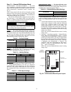
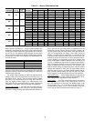
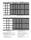
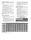
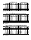
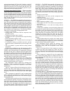
Table 18 — Operating Limits —
50PTH, PTV, PTD Units
LEGEND
NOTE: Value in heating column is dry bulb only. Any wet bulb reading is
acceptable.
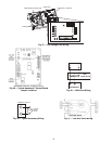
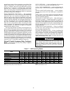
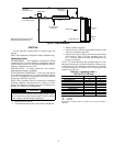
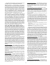
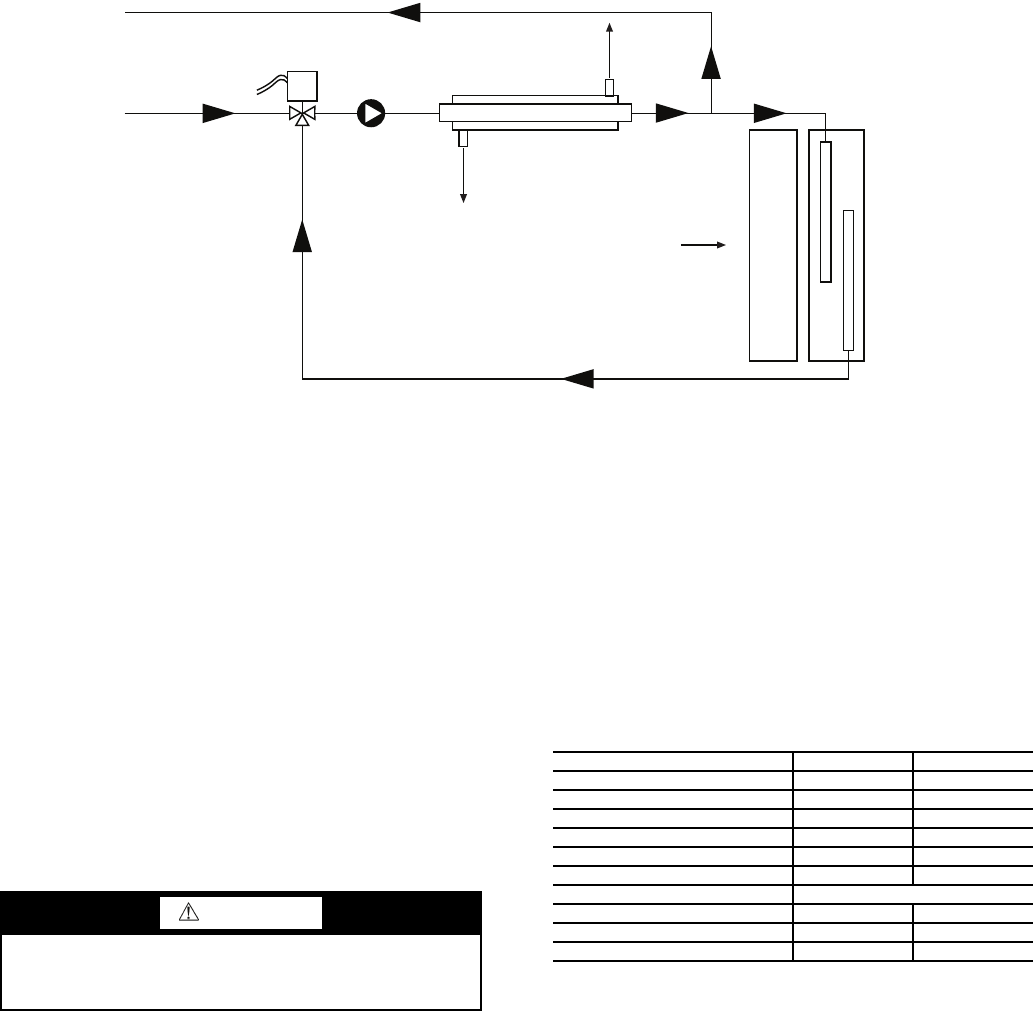
Fig. 33 — HWR Schematic
a50-8145
Water Out
(To Water Loop)
Water In
(From Water Loop)
Mixing Valve
COAX
Evaporator Coil
Reheat
Coil
Refrigerant Out
(Cooling)
Refrigerant In
(Cooling)
Entering Air
Leaving
Air
Internal Pump
NOTE: All components shown are
internal to the heat pump unit.
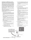
WARNING
When the disconnect switch is closed, high voltage is pres-
ent in some areas of the electrical panel. Exercise caution
when working with the energized equipment.
AIR LIMITS COOLING (F) HEATING (F)
Min. Ambient Air 45 40
Rated Ambient Air 80 70
Max. Ambient Air 100 85
Min. Entering Air 50 40
Rated Entering Air db/wb 80/67 70
Max. Entering Air db/wb 110/83 80
WATER LIMITS
Min. Entering Water 30 20
Normal Entering Water 50-110 30-70
Max. Entering Water 120 90
db — Dry Bulb
wb — Wet Bulb