


28
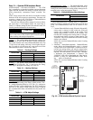
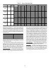
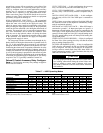
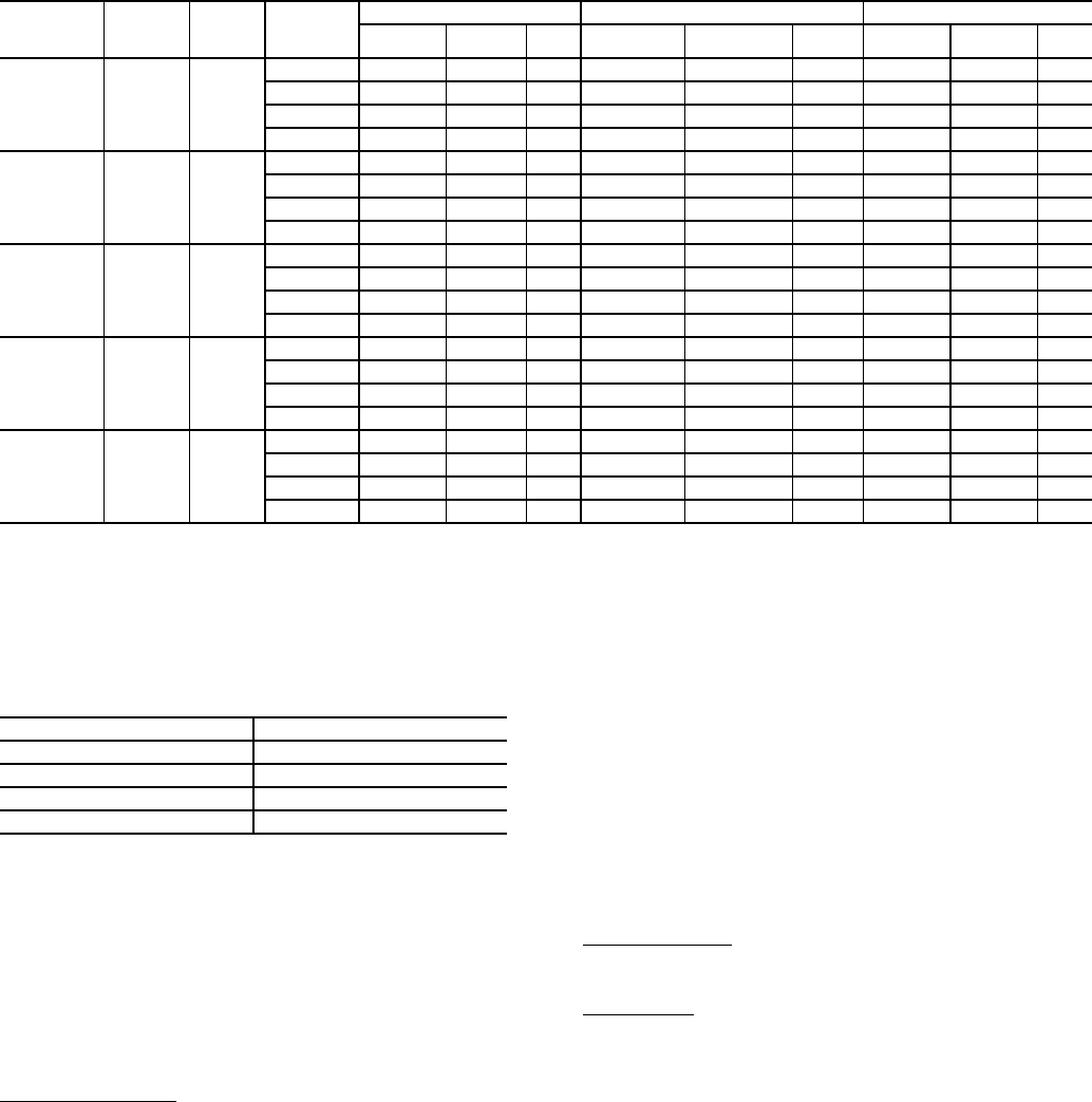
Table 13 — Blower Performance Data
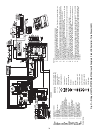
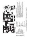
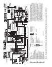
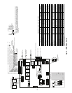
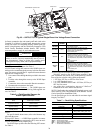
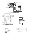
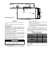
WSHP OPEN CONTROLS — The ECM fan is controlled by
an interface board that converts the fan speed outputs from the
WSHP Open control board to the signal used by the ECM mo-
tor (see Fig 35). The indicator LEDs allow the service techni-
cian to view the airflow mode that the WSHP Open control is
commanding. The table below indicates the illuminated LEDs
for each fan mode.
NOTE: Power must be off to the unit for at least three seconds
before the ECM will recognize a speed change. The motor will
recognize a change in the CFM Adjust setting (SW7 and SW8)
while the unit is powered.
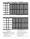
The WSHP Open controller provides four different airflow
settings which can be set between the lowest airflow (tap 1) to
the highest airflow (tap 4). The lowest three airflow settings
(Fan Only, Low, and Medium) are set using SW3 and SW 4
while the highest airflow (High) is set independently using
SW5 and SW6. This provides the ability to better adjust the fan
performance of the unit to meet the required load conditions.
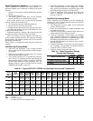
Cooling and Heating
— The SW3 and SW4 DIP switch set-
tings determine the fan airflow (cfm) to be used during normal
Fan Only, Cooling, Heating, and Dehumidification modes (see
Table 14A). The fan speed and airflow is independent from the
compressor capacity control. During Fan Only operation, the
fan will operate at the Fan Only airflow value specified in the
table for the appropriate tap setting. Once either cooling or
heating is required and the compressor is energized, the fan
will increase the minimum airflow across the coil to the value
defined by the low fan selection. Coil freeze protection and ex-
cessive discharge air temperature protection are integral parts
of the WSHP Open controller function so the fan airflow can
increase to medium or high airflow as required and indepen-
dent of compressor capacity to prevent excessively hot or cold
supply air temperature and coil freeze-up. The selection of the
high fan airflow setting is independent of the other fan airflow
settings and is defined in Table 14B. The high airflow must be
chosen so that it is equal to or greater than the medium fan air-
flow. Therefore the tap setting for high fan (SW5 and SW6)
MUST equal or exceed the tap chosen for the SW3 and SW4.
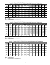
Dehumidification
— When Dehumidification is used, the fan
operates at the airflow setting defined by the Medium Fan air-
flow setting and the tap position of SW3 and SW4.
CFM Adjust
— The CFM Adjust setting allows the balancer
to fine tune the actual airflow. SW7 and SW8 are used to set
the CFM Adjustment if necessary. The NORM setting is the
factory default. The (+) or (-) settings provide the ability to ad-
just the airflow by either +15% or -15% as needed. A test posi-
tion is also provided but should not be used (see Table 11).
50PT
UNIT SIZE
MAX ESP
(in. wg)
FAN
MOTOR
(hp)
TAP
SETTING
COOLING MODE (cfm) DEHUMIDIFICATION MODE (cfm) HEATING MODE (cfm)
Stage 1 Stage 2 Fan Stage 1 Stage 2 Fan Stage 1 Stage 2 Fan
026 0.50
1
/
2
4 810 950 475 630 740 475 920 1060 475
3 725 850 425 560 660 425 825 950 425
2 620 730 370 490 570 370 710 820 370
1 520 610 300 — — — 600 690 300
038 0.50
1
/
2
4 1120 1400 700 870 1090 700 1120 1400 700
3 1000 1250 630 780 980 630 1000 1250 630
2 860 1080 540 670 840 540 860 1080 540
1 730 900 450 — — — 730 900 450
049 0.75 1
4 1460 1730 870 1140 1350 870 1560 1850 870
3 1300 1550 780 1020 1210 780 1400 1650 780
2 1120 1330 670 870 1040 670 1200 1430 670
1 940 1120 560 — — — 1010 1200 560
064 0.75 1
4 1670 2050 1020 1300 1600 1020 1860 2280 1020
3 1500 1825 920 1160 1430 920 1650 2050 920
2 1280 1580 790 1000 1230 790 1430 1750 790
1 1080 1320 660 — — — 1200 1470 660
072 0.75 1
4 1620 2190 1050 1270 1650 1050 1690 2230 1050
3 1500 1950 980 1170 1520 980 1600 2100 980
2 1400 1830 910 1100 1420 910 1400 1850 910
1 1320 1700 850 — — — 1240 1620 850
ECM INDICATORS LEDs SPEED
G Fan Only
G + Y1 Low Fan
G + Y1 + Y2 Med Fan
G + Y1 +W High Fan