


16
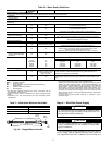
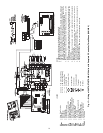
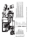
ECM INTERFACE BOARD LAYOUT
Y
GGGGR
W
O
Y
2
Y
1
G
R
C
Y
2
Y
1
G
O
W
C
R
D
H
A
L
1
A
A
A
L1
S
W1
S
W2
S
W3
S
W4
S
W5
S
W6
S
W7
S
W8
S
W9
OF
F
ON
G
D
E
HUM
C
F
M
T
B
1
J1
S
1
BM (ECM)
BM
(ECM)
SW1
S
W2
S
W3
S
W4
S
W5
S
W6
S
W7
S
W8
S
W9
OF
F
O
N
ECM
INTERFACE
BOARD
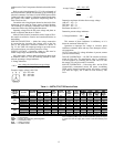
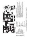
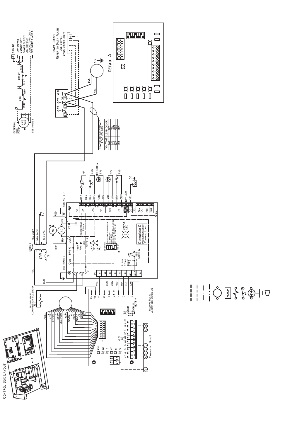
AL — Alarm Relay Contacts
ASTAT — Aquastat
BM — Blower Motor
BR — Blower Relay
CB — Circuit Breaker
CC — Compressor Contactor
CO — Sensor, Condensate Overflow
DTS — Discharge Temp Switch
ECM — Electronically Commutated Motor
FP1 — Sensor, Water Coil Freeze Protection
FP2 — Sensor, Air Coil Freeze Protection
HP — High-Pressure Switch
HWG — Hot Water Generator
JW1 — Jumper, Alarm
LOC — Loss of Charge Pressure Switch
MV — Motorized Valve
NEC — National Electrical Code
P1 — Field Wiring Terminal Block
RVS — Reversing Valve Solenoid
TRANS — Transformer
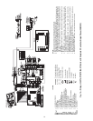
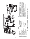
NOTES:
1. Compressor and blower motor thermally protected internally.
2. All wiring to the unit must comply with NEC and local codes.
3. Transformer for 208/230 v will be connected for 208 v operation. For 230 v operation, disconnect
RED lead at L1 and attach ORN lead to L1. Insulate open end of RED lead. Transformer for 220/
240 v will be connected for 220 v operation. For 240 v operation, disconnect RED lead at L1 and
attach ORN lead to L1. Transformer is energy limiting or may have circuit breaker.
4. FP1 thermistor provides freeze protection for water. When using antifreeze solutions, cut JW3
jumper.
5. Typical Aquazone™ thermostat wiring shown. Refer to thermostat installation instructions for wir-
ing to the unit. Thermostat wiring must be Class 1 and voltage rating equal to or greater than unit
supply voltage.
6. 24-v alarm signal shown. For dry alarm contact, cut JW1 jumper and dry contact will be available
between AL1 and AL2.
7. Transformer secondary ground via Complete C board standoffs and screws to control box.
(Ground available from top two standoffs as shown.)
8. Aquastat is field-supplied and must be wired in series with the hot leg to the pump. Aquastat is
rated for voltage up to 277 v.
9. Place jumpers on 2 and 3, ECM board, when dehumidification mode is used.
LEGEND
Field Line Voltage Wiring
Field Low Voltage Wiring
Printed Circuit Trace
Optional Wiring
Relay/Contactor Coil
Condensate Pan
Solenoid Coil
Temperature Switch
Thermistor
Ground
Wire Nut
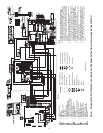
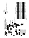
Fig. 17 — Wiring of 50PTH,PTV,PTD026-072 Units with Complete C Controller, Three Phase (208/230 V)