


34
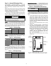
Scroll Compressor Rotation — It is important to be
certain compressor is rotating in the proper direction. To
determine whether or not compressor is rotating in the proper
direction:
1. Connect service gages to suction and discharge pressure
fittings.
2. Energize the compressor.
3. The suction pressure should drop and the discharge
pressure should rise, as is normal on any start-up.
If the suction pressure does not drop and the discharge
pressure does not rise to normal levels:
1. Turn off power to the unit. Install disconnect tag.
2. Reverse any two of the unit power leads.
3. Reapply power to the unit and verify pressures are correct.
The suction and discharge pressure levels should now move
to their normal start-up levels.
When the compressor is rotating in the wrong direction, the
unit makes more noise and does not provide cooling.
After a few minutes of reverse operation, the scroll com-
pressor internal overload protection will open, thus activating
the unit lockout. This requires a manual reset. To reset, turn the
thermostat on and then off.
NOTE: There is a 5-minute time delay before the compressor
will start.
Unit Start-Up Cooling Mode
1. Adjust the unit thermostat to the warmest position.
Slowly reduce the thermostat position until the compres-
sor activates.
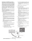
2. Check for cool air delivery at unit grille a few minutes
after the unit has begun to operate.
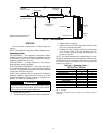
3. Verify that the compressor is on and that the water flow
rate is correct by measuring pressure drop through the
heat exchanger using P/T plugs. See Table 19. Check the
elevation and cleanliness of the condensate lines; any
dripping could be a sign of a blocked line. Be sure the
condensate trap includes a water seal.
4. Check the temperature of both supply and discharge
water. Compare to Tables 20-23. If temperature is within
range, proceed. If temperature is outside the range, check
the cooling refrigerant pressures in Tables 20-23.
5. Check air temperature drop across the coil when com-
pressor is operating. Air temperature drop should be
between 15 and 25 F.
Unit Start-Up Heating Mode
NOTE: Operate the unit in heating cycle after checking the
cooling cycle. Allow 5 minutes between tests for the pressure
or reversing valve to equalize.
1. Turn thermostat to lowest setting and set thermostat
switch to HEAT position.
2. Slowly turn the thermostat to a higher temperature until
the compressor activates.
3. Check for warm air delivery at the unit grille within a few
minutes after the unit has begun to operate.
4. Check the temperature of both supply and discharge
water. Compare to Tables 20-23. If temperature is within
range, proceed. If temperature is outside the range, check
the heating refrigerant pressures in Tables 20-23.
5. Once the unit has begun to run, check for warm air deliv-
ery at the unit grille.
6. Check air temperature rise across the coil when compres-
sor is operating. Air temperature rise should be between
20 and 30 F after 15 minutes at load.
7. Check for vibration, noise and water leaks.
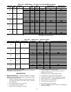
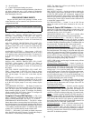
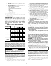
Table 19 — Water Temperature Change
Through Heat Exchanger
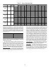
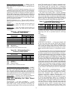
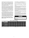
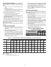
Table 20 — Typical 50PTH,PTV,PTD026 Unit Operating Pressures and Temperatures
LEGEND
WATER FLOW RATE (GPM)
COOLING
RISE (F)
HEATING
DROP (F)
Min Max Min Max
For Closed Loop: Ground Source or
Cooling/Boiler Systems at 3 gpm/ton
91248
For Open Loop: Ground Water Systems at
1.5 gpm/ton
20 26 10 17
ENTERING
WATER
TEMP (F)
(EWT)
WATER
FLOW
(Gpm/Ton)
FULL LOAD COOLING WITHOUT HWG ACTIVE FULL LOAD HEATING WITHOUT HWG ACTIVE
Suction
Pressure
(psig)
Discharge
Pressure
(psig)
Super-
heat
(F)
Sub-
cooling
(F)
Water
Temp
Rise
(F)
Air
Temp
Drop (F)
DB
Suction
Pressure
(psig)
Discharge
Pressure
(psig)
Super-
heat
(F)
Sub-
cooling
(F)
Water
Temp
Drop
(F)
Air
Temp
Rise (F)
DB
30
1.5 118-128 159-179 25-30 9-14 16.7-18.7 19-25 73- 83 273-293 6-11 3- 8 5.9- 7.9 16-22
2.25 118-128 146-166 25-30 7-12 12.3-14.3 20-26 75- 85 275-295 6-11 3- 8 4.2- 6.2 17-23
3 118-128 132-152 25-30 7-12 7.9- 9.9 20-26 78- 88 277-297 6-11 3- 8 2.7- 4.7 18-24
50
1.5 128-138 186-206 18-23 8-13 16.3-18.3 19-25 102-112 302-322 8-12 6-11 8.9-10.9 22-28
2.25 128-138 172-192 18-23 6-11 12.1-14.1 20-26 106-116 303-323 8-12 6-11 6.7- 8.7 23-29
3 128-138 158-178 18-23 6-11 7.8- 9.8 20-26 110-120 305-325 8-12 6-11 4.5- 6.5 23-29
70
1.5 136-146 281-301 7-12 7-12 15.7-17.7 19-25 128-138 330-350 10-15 8-13 11.3-13.3 27-34
2.25 136-146 267-287 7-12 5-10 11.6-13.6 19-25 134-144 332-352 10-15 8-13 8.5-10.5 28-35
3 136-146 253-273 7-12 4- 9 7.6- 9.6 19-25 141-151 334-354 10-15 8-13 5.8- 7.8 28-35
90
1.5 139-149 368-388 6-11 7-12 14.9-16.9 18-24 162-172 367-387 14-19 10-15 14.4-16.4 33-41
2.25 139-149 354-374 6-11 5-10 11.0-13.0 18-24 166-176 372-392 15-20 10-15 10.8-12.8 34-42
3 139-149 340-360 6-11 5-10 7.2- 9.2 18-24 171-181 377-397 17-22 10-15 7.1- 9.1 34-42
110
1.5 143-153 465-485 6-11 7-12 13.9-15.9 17-23 — — — — — —
2.25 143-153 450-470 6-11 5-10 10.2-12.2 17-23 — — — — — —
3 143-153 433-453 6-11 5-10 6.5- 8.5 17-23 — — — — — —
DB — Dry Bulb
HWG — Hot Water Generator
——No heating operation in this temperature range