


9
UNIT DAMAGE HAZARD
Failure to follow this caution may result in equipment
damage.
The correct power phasing is critical to the operation of the
scroll compressors. An incorrect phasing will result in an
alarm being generated and compressor operation lockout.
Should this occur, power phase correction must be made to
the incoming power. Damage to compressor could result.
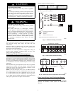
CAUTION
!
ELECTRICAL SHOCK HAZARD
Failure to follow this warning could result in personal
injury or death.
Unit cabinet must have an uninterrupted, unbroken
electrical ground to minimize the possibility of personal
injury if an electrical fault should occur. This ground may
consist of electrical wire connected to unit ground lug in
control compartment, or conduit approved for electrical
ground when installed in accordance with NEC; ANSI
(American National Standards Institute)/NFPA (National
Fire Protection Association), latest edition, and local
electrical codes.
!
WARNING
Field wiring must conform to temperature limitations for type “T”
wire. All field wiring must comply with NEC and local
requirements.
Operating voltage to compressor must be within voltage range
indicated on unit nameplate. On 3--phase units, voltages between
phases must be balanced within 2%.
Unit failure as a result of operation on improper line voltage or
excessive phase imbalance constitutes abuse and may cause
damage to electrical components.
Field Control Wiring (Units Without Optional
Humidi--MiZer
t Adaptive Dehumidification System)
Unit can be controlled with either a Carrier--approved accessory
thermostat or a Carrier--approved space temperature sensor. Install
thermostat according to the installation instructions included with
accessory. Locate thermostat assembly or space temperature sensor
on a solid interior wall in the conditioned space to sense average
temperature.
Route thermostat or space temperature sensor cable or equivalent
single leads of colored wire from subbase terminals through
conduit into unit to low--voltage connections as shown on unit
label wiring diagram and in Fig. 9 or 10.
NOTE: For wire runs up to 50 ft, use no. 18 AWG (American
Wire Gauge) insulated wire (35_C minimum). For 50 to 75 ft, use
no. 16 AWG insulated wire (35_C minimum). For over 75 ft, use
no. 14 AWG insulated wire (35_C Minimum). All wire larger than
no. 18 AWG cannot be directly connected at the thermostat and
will require a junction box and splice at the thermostat.
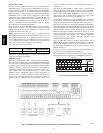
Set heat anticipator settings as follows:
VOLTAGE
Stage 1
(W1) ON
STAGE 1 AND 2
(W1 AND W2) ON
All 0.2 0.4
Settings may be changed slightly to provide a greater degree of
comfort for a particular installation.
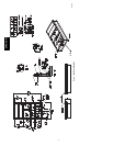
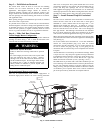
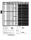
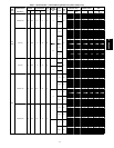
DISCONNECT
PER NEC
FACTOR
POWER
WIRING
FIELD
POWER
WIRING
11
12
13
21
22
23
EQUIP GND
C.A1
LEGEND
C.A1 -- Compressor Contactor (A1)
EQUIP -- Equipment
GND -- Ground
NEC -- National Electrical Code
NOTE: The maximum wire size for C.A1 is 2/0.
C06237
Fig. 8 -- Field Power Wiring Connections
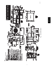
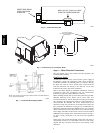
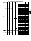
TB1
REMOVABLE JUMPER
THERMOSTAT ASSEMB Y
RH
RC
Y1 Y2
W1 W2 G C
L
X
R
Y1 Y2
W1 W2 G C X
ROOFTOP UNIT
C06292
Fig. 9 -- Field Control Thermostat Wiring
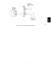
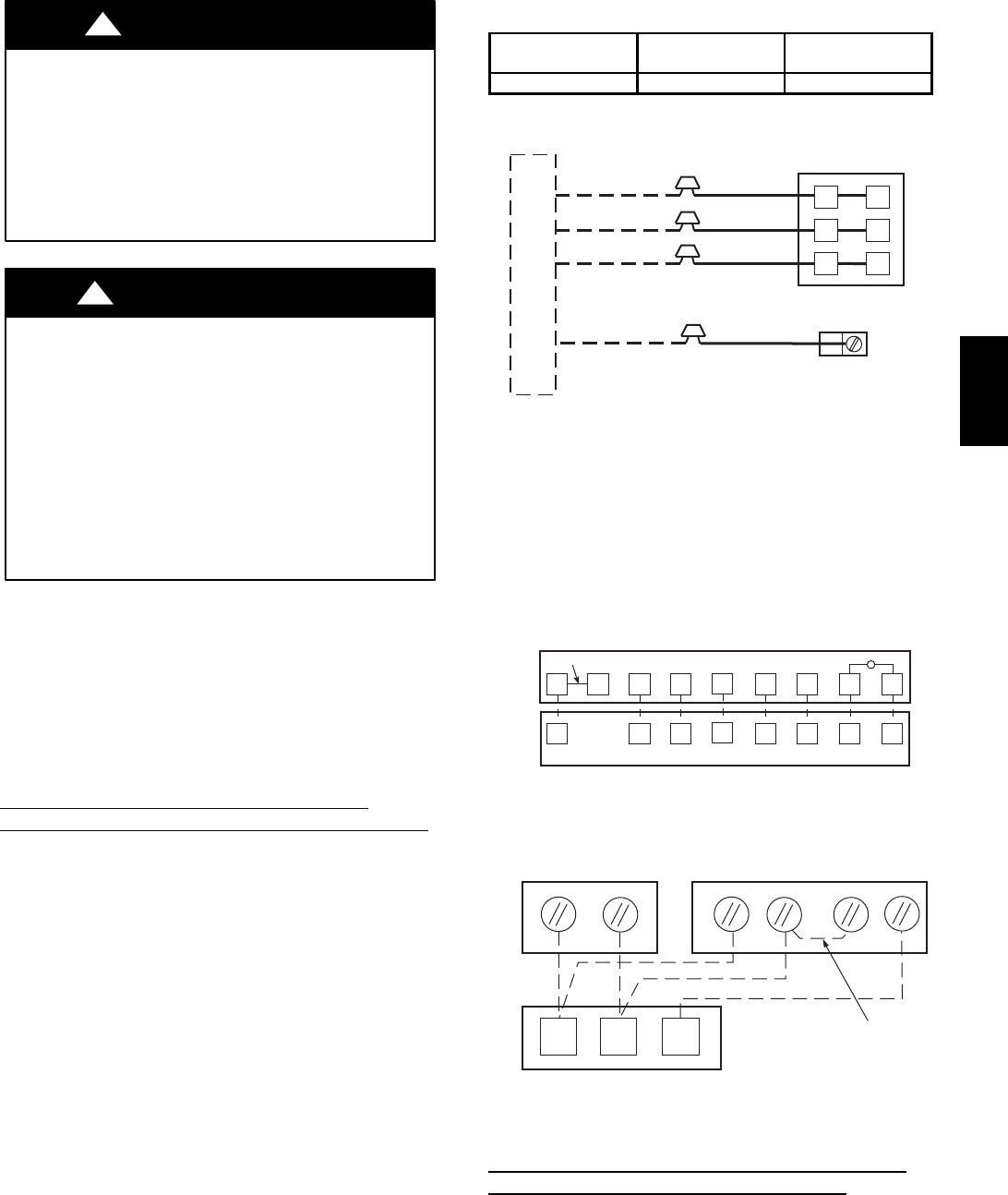
12 3
T-55 SPT
T-56 SPT
T55
TB1
RED
BLACK
RED
BLACK
WHITE
JUMPER
SEN
SET
SEN
ROOFTOP UNIT
C06239
Fig. 10 -- Field Control Space Temperature Sensor Wiring
Field Control Wiring (Units With Optional Humidi--
MiZer
t Adaptive Dehumidification System)
Units require temperature control inputs for cooling and heating
operation and humidity control inputs for Humidi--MiZer
operation.
50PG03--07