


16
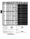
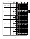
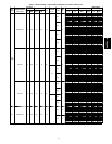
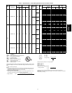
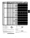
Table 2 -- Electrical Data -- Units Without Optional Convenience Outlet (cont)
UNIT
50PG
NOMINAL
POWER SUPPLY
Volts-Ph-Hz
VOLTAGE
RANGE
COMPRESSOR
OFM
FLA
POWER
EXHAUST
FLA
IFM
TYPE
IFM
FLA
ELECTRIC HEAT POWER SUPPLY
DISCONNECT
SIZE
Min Max RLA LRA FLA
Nominal
kW*
MCA MOCP† FLA LRA
07
(cont)
208/230-3-60 187 253 20.5 149 1.5 1.4
Low 5.2
— — 33.7/33.7 35/35 33/33 184/184
10.0/11.5 3.8/ 5.0 33.7/33.7 35/35 33/33 184/184
15.0/17.3 5.6/ 7.5 33.7/33.7 35/35 33/33 184/184
20.0/23.1 7.5/10.0 33.7/37.1 35/40 33/34 184/184
30.0/34.6 11.3/15.0 45.8/51.5 50/60 42/47 184/184
40.0/46.2 15.0/20.0 58.3/66.0 60/70 54/61 184/184
50.0/57.7 18.8/25.0 70.8/80.4 80/90 65/74 184/184
High 7.5
— — 36.0/36.0 40/40 36/36 210/210
10.0/11.5 3.8/ 5.0 36.0/36.0 40/40 36/36 210/210
15.0/17.3 5.6/ 7.5 36.0/36.0 40/40 36/36 210/210
20.0/23.1 7.5/10.0 36.1/40.0 40/45 36/37 210/210
30.0/34.6 11.3/15.0 48.6/54.4 50/60 45/50 210/210
40.0/46.2 15.0/20.0 61.1/68.9 70/70 56/63 210/210
50.0/57.7 18.8/25.0 73.6/83.3 80/90 68/77 210/210
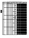
460-3-60 414 506 9.6 75 0.8
—
Low 2.6
— — 15.4 20 15 92
5.8 5.0 15.4 20 15 92
8.7 7.5 15.4 20 15 92
11.5 10.0 17.6 20 16 92
17.3 15.0 24.9 25 23 92
23.1 20.0 32.1 35 30 92
28.9 25.0 39.4 40 36 92
High 3.4
— — 16.2 20 16 105
5.8 5.0 16.2 20 16 105
8.7 7.5 16.2 20 16 105
11.5 10.0 18.6 20 17 105
17.3 15.0 25.9 30 24 105
23.1 20.0 33.1 35 30 105
28.9 25.0 40.4 45 37 105
0.6
Low 2.6
— — 16.0 20 16 93
5.8 5.0 16.0 20 16 93
8.7 7.5 16.0 20 16 93
11.5 10.0 18.4 20 17 93
17.3 15.0 25.6 30 24 93
23.1 20.0 32.9 35 30 93
28.9 25.0 40.1 45 37 93
High 3.4
— — 16.8 20 17 106
5.8 5.0 16.8 20 17 106
8.7 7.5 16.8 20 17 106
11.5 10.0 19.4 20 18 106
17.3 15.0 26.6 30 24 106
23.1 20.0 33.9 35 31 106
28.9 25.0 41.1 45 38 106
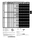
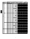
575-3-60 518 633 7.6 54 0.8
—
Low 2.0
— — 12.3 15 12 67
9.2 10.0 14.0 15 13 67
13.9 15.0 19.9 20 18 67
18.5 20.0 25.6 30 24 67
23.1 25.0 31.4 35 29 67
27.7 30.0 37.1 40 34 67
High 2.8
— — 13.1 15 13 78
9.2 10.0 15.0 15 14 78
13.9 15.0 20.9 25 19 78
18.5 20.0 26.6 30 24 78
23.1 25.0 32.4 35 30 78
27.7 30.0 38.1 40 35 78
1.4
Low 2.0
— — 13.7 15 14 69
9.2 10.0 15.8 20 14 69
13.9 15.0 21.6 25 20 69
18.5 20.0 27.4 30 25 69
23.1 25.0 33.1 35 30 69
27.7 30.0 38.9 40 36 69
High 2.8
— — 14.5 15 14 80
9.2 10.0 16.8 20 15 80
13.9 15.0 22.6 25 21 80
18.5 20.0 28.4 30 26 80
23.1 25.0 34.1 35 31 80
27.7 30.0 39.9 40 37 80
LEGEND
FLA --- Full Load Amps
HACR --- Heating, Air Conditioningand Refrigeration
IFM --- Indoor(Evaporator) FanMotor
LRA --- Locked Rotor Amps
MCA --- MinimumCircuitAmps
MOCP --- Maximum Overcurrent Protection
NEC --- National Electrical Code
OFM --- Outdoor (Condenser)FanMotor
RLA --- RatedLoadAmps
*Heatercapacity (kW)is basedon heatervoltage of208v, 240v, 480v, or600v. Ifpower
distribution voltage to unitvariesfromrated heatervoltage,heaterkW will vary accord-
ingly.
{ Fuse or HACR circuit breaker .
NOTES:
1. In c ompliance withNECrequirementsfor multimotorandcombinationloadequipment(refer
toNECArticles430and440),theovercurrentprotectivedevicefortheunitshallbefuse or
HACRbreaker. Canadianunitsmaybefuse or circuitbreaker.
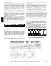
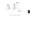
2. Unbalanced3-Phase Supply Voltage
Neveroperate amotorwhereaphaseimbalance insupply v oltageisgreaterthan 2%.Use
thefollowing formulatodetermine the percentageof voltageimbalance.
%VoltageImbalance =100x
maxvoltagedeviatio nfromaveragevoltage
average v oltage
Example: Supply voltage is 230---3---60
AB=224v
BC=231v
AC=226v
Average Voltage=
224+231+226
3
681
3
=
227
=
Determinemaximumdeviation from average voltage.
(AB)227–224 =3v
(BC) 231–227=4v
(AC)227–226 =1v
Maximumdeviationis4v.
Determinepercentof voltage imbalance.
%VoltageImbalance = 100x
4
227
=1.76%
Thisamountof phase imbalance issatisfactory asitisbelow themaximum allowable2%.
IMPORTANT: If the supply voltage phase imbalance is more than 2%, contact your local electric
utilitycompany immediately.
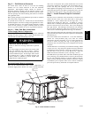
50PG03--07