


4
INSTALLATION
Step 1 — Provide Unit Support
Roof Curb
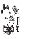
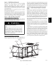
Assemble or install accessory roof curb in accordance with
instructions shipped with this accessory. (See Fig. 1.) Install
insulation, cant strips, roofing, and counter flashing as shown.
Ductwork can be installed to roof curb before unit is set in place.
Ductwork must be attached to curb and not to the unit. Curb must
be level. This is necessary to permit unit drain to function properly.
Unit leveling tolerance is 1/16--in. per linear ft in any direction.
Refer to Accessory Roof Curb Installation Instructions for
additional information as required. When accessory roof curb is
used, unit may be installed on class A, B, or C roof covering
material. Carrier roof curb accessories are for flat roofs or slab
mounting.
IMPORTANT: The gasketing of the unit to the roof curb is critical
for a watertight seal. Install gasket with the roof curb as shown in
Fig. 1. Improperly applied gasket can also result in air leaks and
poor unit performance. Do not slide unit to position on roof curb.
Alternate Unit Support
When a curb cannot be used, install unit on a noncombustible
surface. Support unit with sleepers, using unit curb support area. If
sleepers cannot be used, support long sides of unit with a minimum
of 3 equally spaced 4--in. x 4--in. pads on each side.
Step 2 — Rig and Place Unit
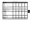
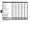
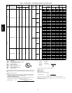
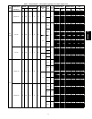
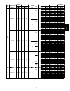
Inspect unit for transportation damage. See Table 1 for physical
data. File any claim with transportation agency.
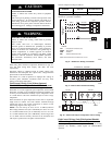
PERSONAL INJURY AND PROPERTY DAMAGE HAZARD
Failure to follow this caution may result in damage to roof.
All panels must be in place when rigging. Unit is not
designed for handling by fork truck.
CAUTION
!
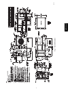
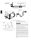
Do not drop unit; keep upright. Use spreader bars over unit to
prevent sling or cable damage. Rollers may be used to move unit
across a roof. Level by using unit rail as a reference; leveling
tolerance is ± 1/16--in. per linear ft in any direction. See Fig. 3 for
additional information. Unit rigging weight is shown in Fig. 3.
Rigging holes are provided in the unit base rails as shown in Fig. 3.
Refer to rigging instructions on unit.
Positioning
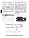
Maintain clearance, per Fig. 2, around and above unit to provide
minimum distance from combustible materials, proper airflow, and
service access. See Fig. 4 for location of access panels.
Do not install unit in an indoor location. Do not locate air inlets
near exhaust vents or other sources of contaminated air.
Although unit is weatherproof, guard against water from higher
level runoff and overhangs.
After unit is in position, remove crating and polyethylene sheet.
Roof Mount
Check building codes for weight distribution requirements. Unit
operating weight is shown in Table 1.
Installation Onto Curb
The 50PG units are designed to fit on the accessory full perimeter
curb. In either case, correct placement of the unit onto the curb is
critical to operating performance. To aid in correct positioning,
place unit on roof curb to maintain 1/4--in. gap between the inside
of rail and roof curb on long sides and a 1/2--in. gap between the
inside of rail and roof curb on both duct and condenser ends. Refer
to Fig. 1 and 3, to assure proper duct opening alignment.
NOTE: Before positioning unit onto curb, refer to Step 5 -- Install
External Trap for Condensate Drain section concerning bottom
drain connection plug.
UNIT DAMAGE HAZARD
Failure to follow this caution may result in equipment
damage.
Do not slide unit to position when it is sitting on the curb.
Curb gasketing material may be damaged and leaks may
result.
CAUTION
!
Slab Mount (Horizontal Units Only)
Provide a level concrete slab that extends a minimum of 6--in.
beyond unit cabinet. Install a gravel apron in front of
condenser--coil air inlet to prevent grass and foliage from
obstructing airflow.
NOTE: Horizontal units may be installed on a roof curb if
required.
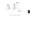
Hook rigging shackles through holes in base rail, as shown in
Detail A. Holes in base rails are centered around the unit
center of gravity. Use wooden top skid, when rigging, to
prevent rigging straps from damaging unit.
CAU OTI
ACCESS PANEL MUST BE IN PLACE WHEN RIGGING.
N- NOTICE TO R GGERS:I
UNIT
SIZE
A B C D E MAX. WEIGHT
in. mm in. mm in. mm in. mm in. mm lb kg
03-07 77.9 1978 36-54 914-1371 44.8 1139 42.0 1067 23.5 597 1156 52
5
C07270
Fig. 3 -- 50PG Rigging Label
50PG03--07