


7
Step 3 — Field Fabricate Ductwork
On vertical units, secure all ducts to roof curb and building
structure. Do not connect ductwork to unit. For horizontal
applications, field--supplied flanges should be attached to
horizontal discharge openings and all ductwork secured to the
flanges. Insulate and weatherproof all external ductwork, joints,
and roof openings with counter flashing and mastic in accordance
with applicable codes.
Ducts passing through an unconditioned space must be insulated
and covered with a vapor barrier.
If a plenum return is used on a vertical unit, the return should be
ducted through the roof deck to comply with applicable fire codes.
A minimum clearance is not required around ductwork. Cabinet
return--air static pressure (a negative condition) shall not exceed
0.35--in. wg with economizer or 0.45--in. wg without economizer.
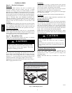
Step 4 — Make Unit Duct Connections
Vertical Supply/Return Configuration
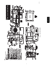
Unit is shipped in vertical supply/return configuration. Ductwork
openings are shown in Fig. 1 and 3. Attach the ductwork to the
roof curb. Do not attach duct directly to the unit.
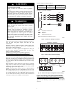
PERSONAL INJURY HAZARD
Failure to follow this warning could result in personal
injury.
For vertical supply and return units, tools or parts could
drop into ductwork and cause an injury. Install a
90--degree turn in the return ductwork between the unit
and the conditioned space. If a 90--degree elbow cannot
be installed, then a grille of sufficient strength and
density should be installed to prevent objects from
falling into the conditioned space.
!
WARNING
Horizontal Supply/Return Applications
Unit can be field--converted from vertical supply/return to
horizontal supply/return. Remove all screws securing horizontal
duct covers to duct panel. Save panels. Install duct covers in the
vertical duct openings in the basepan with the insulation side up.
Covers will drop into openings and can be secured using
field--supplied self--tapping screws. Ductwork can be attached to
duct flanges provided on unit. When securing ductwork to unit, do
not drill in area below bead or above top edge of duct opening.
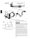
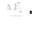
Step 5 — Install External Trap for Condensate
Drain
The unit’s 3/4--in. condensate drain connections are located on the
bottom and side of the unit. If the down drain is used, drill a
minimum of a 5/8-in. diameter hole but not larger than a
3
/
4
-in.
diameter hole through the drain pan. A dimple of 2 mm in
diameter and 1.5 mm deep will be provided in the drain pan to help
locate the drill bit and to start the hole. Do not cut through the
PVC pipe threads. Unit discharge connections do not determine
the use of drain connections; either drain connection can be used
with vertical or horizontal applications. See Fig. 2 for locations.
When using the standard side drain connection, make sure the plug
(red) in the alternate bottom connection is tight before installing the
unit. (See Fig. 5.)
To use the bottom drain connection for a roof curb installation,
relocate the factory--installed plug (red) from the bottom
connection to the side connection. A 1/2--in. socket extension can
be used to remove the plug. (See Fig. 5.) The piping for the
condensate drain and external trap can be completed after the unit
is in place.
All units must have an external trap for condensate drainage. Install
a trap at least 4--in. deep and protect against freezeup. If drain line
is installed downstream from the external trap, pitch the line away
from the unit at 1--in. per 10 ft of run. Do not use a pipe size
smaller than the unit connection (3/4--in.). (See Fig. 6 and 7.)
The 50PG units are provided with a removable condensate pan for
ease of cleaning. It is recommended that a union be placed between
the unit and condensate drainage to ease the removal of the pan
during servicing. Adequate clearance should be allowed if removal
of condensate pan is required. Allow 54--in. between condensate
pan access panel and any obstruction for complete removal.
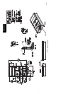
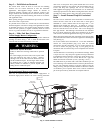
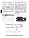
CONTROL BOX
AND
COMPRESSOR
OUTDOOR AIR
SCREEN
(HIDDEN)
FILTER ACCESS DOOR
INDOOR MOTOR
ACCESS DOOR
ECONOMIZER
HOOD
BAROMETRIC
RELIEF DAMPER
HOOD
ELECTRICAL
OPTIONS PANEL
BASEPAN CONNECTIONS
ACCESS PANEL
CONDENSER COIL
ACCESS PANEL
ELECTRIC HEAT
ACCESS DOOR
C07272
Fig. 4 -- Panel and Filter Locations
50PG03--07