


10
Temperature Control
The unit can be controlled with either a Carrier--approved space
temperature sensor, a Carrier accessory Thermidistatt device, or a
Carrier--approved accessory thermostat. Install the temperature
control device according to the installation instructions included
with the accessory. Locate the device on a solid interior wall in the
conditioned space to sense average temperature. Carrier space
temperature sensor wiring connections are shown in Fig. 10.
General thermostat field control wiring connections are shown in
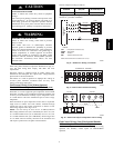
Fig. 9. Carrier Thermidistat device wiring connections are shown
in Fig. 11. Configuration of the unit control is required to specify
the control input type before unit operation.
Route thermostat or space temperature sensor cable or equivalent
single leads of colored wire from subbase terminals through
conduit into unit to low--voltage connections as shown on unit
label wiring diagram and in Fig. 9--11.
NOTE: For wire runs up to 50 ft, use no. 18 AWG (American
Wire Gauge) insulated wire (35_C minimum). For 50 to 75 ft, use
no. 16 AWG insulated wire (35_C minimum). For over 75 ft, use
no. 14 AWG insulated wire (35_C Minimum). All wire larger than
no. 18 AWG cannot be directly connected at the thermostat and
will require a junction box and splice at the thermostat.
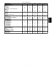
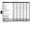
Set heat anticipator settings as follows:
VOLTAGE
Stage 1
(W1) ON
STAGE 1 AND 2
(W1 AND W2) ON
All 0.2 0.4
Settingsmay be changed slightly to provide a greater degree of
comfort for a particular installation.
Humidity Control
Unit can be controlled with either a Carrier accessory Thermidistat
device or a Carrier--approved accessory humidistat (switch output).
The input for an accessory humidity sensor with 4 to 20 mA output
is another option available when an economizer board is installed.
Install the humidity control device according to the installation
instructions included with the accessory. Locate the device on a
solid interior wall in the conditioned space to sense average
humidity. Carrier Thermidistat device wiring connections are
shown in Fig. 11. General humidistat wiring connections are
shown in Fig. 12. Configuration of the unit control is required to
specify the control input type before unit operation. Refer to the
Controls, Start--up, Operation and Troubleshooting manual for
configuration.
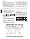
Units with the Humidi--MiZert option receive a discrete input
from a field--installed device (such as from the Carrier humidistat
or Thermidistat device). The discrete input is connected to the TB1
terminal strip points labeled Humidistat 1 and 2. As this is a
discrete input, one of the connection points is for power to the
switch and the other is the return path. (See Fig. 12.)
A space relative humidity sensor input (SP.RH) is only available if
an economizer board (ECB) is installed in the unit and then the
sensor can be connected to the OAQ point TB1--4. (See Fig. 12.)
This input is used instead of the discrete humidistat or thermidistat
inputs. The input controls the Humidi--MiZer using the 4 to 20 mA
as percent humidity. The relative humidity value (measured by the
relative humidity sensor) can be displayed on the Scrolling
Marquee, in the space through a System Pilott device, or can be
read by other CCN devices where it can be used to perform more
advanced functions. The humidity sensor must be configured
correctly; refer to the Controls, Start--up, Operation, and
Troubleshooting manual for details.
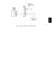
If the customer also wishes to install a smoke detector into a
Humidi--MiZer equipped 50PG unit, the fire shutdown connection
points are on Plug PL--19, located in the economizer section. See
the unit wiring schematic for wiring. For third--party smoke
detector, see Fig. 13.
Point 19--3 is the 24 vac power source for the detector and point
19--5 is the 24 vac signal input for fire shutdown.
More information is available in the third party control section of
the Controls, Start--up, Operation, and Troubleshooting manual.
OC
RY1
Y2
W1
W2
G
C
DEHUM
5
R
Y1
Y2
W1
W2
G
C
1
2
HUMIDISTAT
ROOFTOP UNIT
TB1
THERMIDISTAT
C07055
Fig. 11 -- Field Control Thermidistat Wiring
C07045
Fig. 12 -- Humidi--MiZer Low--Voltage Terminal Strip -- Humidity Sensor/Humidity Wiring
50PG03--07