


8
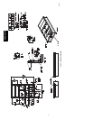
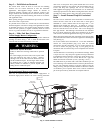
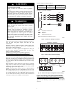
INSERT SIDE DRAIN
PLUG FOR DOWN
DRAIN USE.
DRILL 5/8” DIA. (0.625 mm) HOLE
THRU FOR DOWN DRAIN USE.
C10321
Fig. 5 -- Condensate Drain Pan
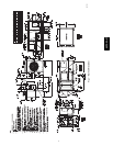
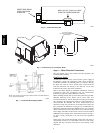
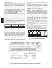
OPTIONAL UNIONS
TO ALLOW FOR CONDENSATE
PAN REMOVAL
4" (102mm)
CONDENSATE
PAN ACCESS
PANEL
C06234
Fig. 6 -- External Trap for Condensate Drain
NOTE: Trap should be deep enough to offset maximum unit static difference.
A
4-in. trap is recommended.
C06291
Fig. 7 -- Condensate Drain Piping Details
Step 6 — Make Electrical Connections
(For more details, refer to the Controls, Start--up, Operation, and
Troubleshooting manual).
Field Power Supply
All 208/230--v units are factory wired for 230--v power supply. If
the 208/230--v unit is to be connected to a 208--v power supply, the
transformers (TRAN1 and TRAN2) must be rewired by moving
the black wire with the 1/4--in. female quick connect from the
230--volt connection and moving to the 200--volt 1/4--in. male
terminal on the primary side of the transformer.
Refer to unit label diagram for additional information. Leads are
provided for field wire connections. Use UL (Underwriters
Laboratories) approved copper/aluminum connector.
When installing rooftop units, provide safety disconnect per NEC
(National Electrical Code) Article 440 or local codes. For
non--fused disconnects, size the disconnect according to the sizing
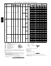
data provided in the electrical data tables. If a fused disconnect is
used, determine the minimum size for the switch based on the
disconnect sizing data provided in the electrical data tables and
then coordinate the disconnect housing size to accommodate the
Maximum Overcurrent Protection (MOCP) device size as marked
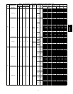
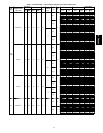
on the unit informative plate. (See Table 2 and 3.) All field wiring
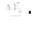
must comply with NEC and local codes. Size wire based on MCA
(Minimum Circuit Amps) on the unit informative plate. See Fig. 8
for power wiring connection to the unit leads and equipment
ground.
Route power and ground lines through control box end panel or
unit basepan (see Fig. 2) to connections as shown on unit wiring
diagram and Fig. 8. Factory leads may be wired directly to the
disconnect.
50PG03--07