


9
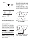
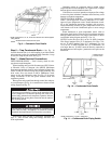
Step 6 — Trap Condensate Drain —
See Fig. 10
for drain location. One
3
/
4
-in. half coupling is provided outside
unit evaporator section for condensate drain connection. A trap
at least 4-in. deep must be used. See Fig. 11.
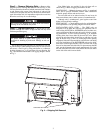
Step 7 — Make Electrical Connections
FIELD POWER SUPPLY — Unit is factory wired for volt-
age shown on unit nameplate.
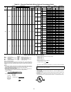
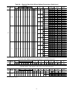
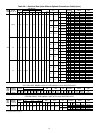
When installing units, provide disconnect per NEC (Nation-
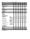
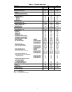
al Electrical Code) of adequate size (MOCP [Maximum
Overcurrent protection] of unit is on the informative plate). See
Tables 2A and 2B. All field wiring must comply with NEC and
local codes. Size wire based on MCA (Minimum Circuit
Amps) on the unit informative plate. See Fig. 12 for power
wiring connections to the unit power terminal block and
equipment grounds.
Route power and ground lines through control box end pan-
el or unit basepan (see Fig. 4) to connections as shown on unit
wiring diagram and Fig. 12.
Field wiring must conform to temperature limitations for
type ‘‘T’’ wire. All field wiring must comply with NEC and
local requirements.
Operating voltage to compressor must be within voltage
range indicated on unit nameplate. On 3-phase units, voltages
between phases must be balanced within 2%.
Unit failure as a result of operation on improper line voltage
or excessive phase imbalance constitutes abuse and may cause
damage to electrical components.
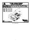
FIELD CONTROL WIRING — Unit can be controlled with
either a Carrier-approved accessory thermostat or a Carrier-
approved space temperature sensor. Install thermostat accord-
ing to the installation instructions included with accessory.
Locate thermostat assembly or space temperature sensor on a
solid interior wall in the conditioned space to sense average
temperature.
Route thermostat or space temperature sensor cable or
equivalent single leads of colored wire from subbase terminals
through conduit into unit to low-voltage connections as shown
on unit label wiring diagram and in Fig. 13 or 14.
NOTE: For wire runs up to 50 ft, use no. 18 AWG (American
Wire Gage) insulated wire (35 C minimum). For 50 to 75 ft,
use no. 16 AWG insulated wire (35 C minimum). For over
75 ft, use no. 14 AWG insulated wire (35 C Minimum). All
wire larger than no. 18 AWG cannot be directly connected at
the thermostat and will require a junction box and splice at the
thermostat.
The correct power phasing is critical to the operation of the
scroll compressors. An incorrect phasing will result in an
alarm being generated and compressor operation lockout.
Should this occur, power phase correction must be made to
the incoming power.
The unit must be electrically grounded in accordance with
local codes and NEC ANSI/NFPA 70 (American National
Standards Institute/National Fire Protection Association).
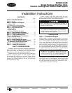
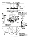
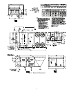
NOTE: Dimensions A, A′,B,andB′
are obtained from field-supplied
c
eiling diffuser.
Shaded areas indicate block-off pans.
Fig. 9 — Concentric Duct Details
Fig. 10 — Condensate Drain Details
NOTE: Dimensions in [] are in millimeters.
Fig. 11 — Condensate Drain Piping Details