


8
Step 4 — Field Fabricate Ductwork —
Secure all
ducts to building structure. Use flexible duct connectors be-
tween unit and ducts as required. Insulate and weatherproof all
external ductwork, joints, and roof openings with counter
flashing and mastic in accordance with applicable codes.
Ducts passing through an unconditioned space must be in-
sulated and covered with a vapor barrier.
Step 5 — Make Unit Duct Connections
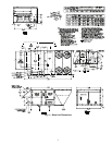
VERTICAL CONFIGURATION — Unit is shipped for thru-
the-bottom duct connections. Ductwork openings are shown in
Fig. 1 and 4. Duct connections for vertical supply and return
configuration are shown in Fig. 7. Field fabricated concentric
ductwork may be connected as shown in Fig. 8 and 9. The unit
is designed to attach the ductwork to the roof curb. Do not
attach duct directly to the unit basepans.
Unit basepans must be supported under the unit and around
duct openings in order to prevent air leakage.
Units with electric heat require a 1-in. clearance for the first
24 in. of ductwork. Outlet grilles must not lie directly below
unit discharge.
NOTE: A 90-degree elbow must be provided in the supply
ductwork to comply with UL (Underwriters’ Laboratories)
codes for use with electric heat.
HORIZONTAL APPLICATIONS — Horizontal units are
shipped with outer panels that allow for side by side horizontal
duct connections. If specified during ordering, the unit will be
shipped with the vertical duct openings blocked off from the
factory, ready for side supply installation. If the horizontal
option was not specified at time of ordering the unit, a field-
installed accessory kit is required to convert the vertical unit
into a horizontal supply configuration.
Installation of the duct block-off covers should be complet-
ed prior to placing the unit unless sufficient side clearance is
available. A minimum of 66-in. is required between the unit
and any obstruction to install the duct block-off covers. Side
supply duct dimensions and locations are shown on Fig. 4.
Connect ductwork to horizontal duct flange connections on
side of unit.
For vertical supply and return units, tools or parts could
drop into ductwork and cause an injury. Install a 90-degree
turn in the return ductwork between the unit and the condi-
tioned space. If a 90-degree elbow cannot be installed, then
a grille of sufficient strength and density should be installed
to prevent objects from falling into the conditioned space.
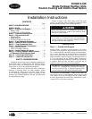
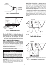
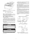
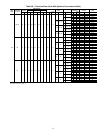
ALIGNMENT
HOLE SHOULD
LINE UP WITH
ROOF CURB
EDGE FLANGE
EDGE FLANGE
ALIGNMENT
HOLE
(IN BASE RAIL)
SUPPLY
OPENING
RETURN
OPENING
ALIGNMENT
HOLES FOR
HJ, TJ, DP, DR
CURB-BOTH
SIDES
ROOF CURB
CURB
SUPPLY
OPENING
CURB
RETURN
OPENING
ALIGNMENT
HOLES FOR HG
CURB-BOTH
SIDES
Fig. 5 — Alignment Hole Details
Fig. 6 — Alignment Hole Location
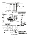
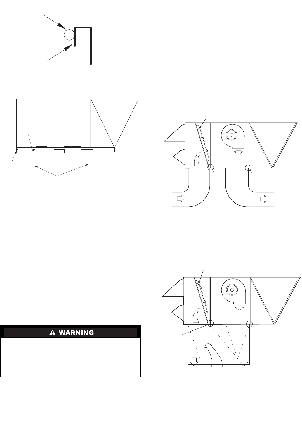
SEE
NOTE
SEE
NOTE
AIR OUT
AIR IN
AIR OUT
ECONOMIZER
NOTE: Do not drill in this area; damage to basepan may result in
water leak.
Fig. 7 — Air Distribution —
Vertical Supply and Return
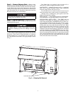
NOTE: Do not drill in this area; damage to basepan may result in
water leak.
Fig. 8 — Air Distribution — Concentric Duct
SEE
NOTE
SEE
NOTE
AIR
OUT
AIR
IN
ECONOMIZER