


3
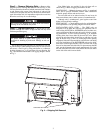
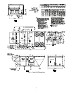
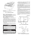
Step 2 — Remove Shipping Rails —
Remove ship-
ping rails prior to lowering unit onto roof curb. See Fig. 2. The
rails are attached to the unit at both the return end and condens-
er end. Remove the screws from both ends of each rail. Be
careful not to drop the rails onto any surface that could be dam-
aged. Discard the rails. It is important to replace the screws into
the unit to avoid any air or water leakage.
Step 3 — Rig and Place Unit —
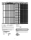
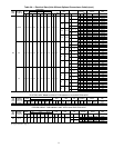
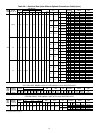
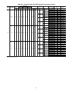
Inspect unit for trans-
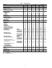
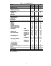
portation damage. See Table 1 for physical data. File any claim
with transportation agency.
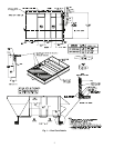
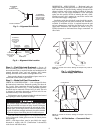
Do not drop unit; keep upright. Use spreader bars over unit
to prevent sling or cable damage. Rollers may be used to move
unit across a roof. Level by using unit frame as a reference;
leveling tolerance is ±
1
/
16
in. per linear ft in any direction. See
Fig. 3 for additional information. Unit rigging weight is shown
in Fig. 3.
Four lifting holes are provided in the unit base rails as
shown in Fig. 3. Refer to rigging instructions on unit.
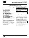
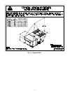
POSITIONING — Maintain clearance, per Fig. 4, around and
above unit to provide minimum distance from combustible
materials, proper airflow, and service access.
Do not install unit in an indoor location. Do not locate air
inlets near exhaust vents or other sources of contaminated air.
Although unit is weatherproof, guard against water from
higher level runoff and overhangs.
ROOF MOUNT — Check building codes for weight distribu-
tion requirements. Unit operating weight is shown in Table 1.
INSTALLATION ONTO CURB — The 50HG units are
designed to fit on either the accessory full perimeter curb or
onto existing 48/50TJ,HJ or 48/50DP,DR curbs. In either case,
correct placement of the unit onto the curb is critical to operat-
ing performance. To aid in correct positioning,
3
/
8
-in. diameter
locating holes have been added to the unit base rails. When
placing the unit, these holes should line up with the roof curb
edge as shown in Fig. 5 and 6, to assure proper duct opening
alignment. Select the alignment holes suited for the curb being
used. For installation on the HJ/TJ/DP/DR curb use the align-
ment holes located approximately 20 in. from the end of the
base rail on the return end of the unit. For placement on the HG
curb, use the alignment holes located approximately 2-in. from
the end of the base rail on the return end of the unit. See labels
on the side of the unit for more details.
Do not allow the shipping rail to drop on the roof surface.
Damage to the roof surface may result.
All panels must be in place when rigging. Unit is not
designed for handling by fork truck. Damage to unit can
result.
SHIPPING RAILS
Fig. 2 — Shipping Rail Removal