


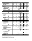
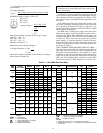
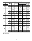
Table 1 — Physical Data
UNIT 48MA/50ME 016 024 028 030 034 040
Zone Modules (Quantity) 8 8 10 10 12 12
Nominal Cooling Capacity (tons) 15 20 25 28 30 37
OPERATING WEIGHT (lb)
Base Unit 48MA 3395 3815 4075 4080 5340 5710
Base Unit 50ME (with electric heat) 2995 3415 3675 3680 4900 5270
Roof Curb 506 506 506 506 630 630
REFRIGERANT CHARGE — R-22 (lb) 28 32 43 43 57 66.1
COMPRESSOR Reciprocating Hermetic, 1725 Rpm
No. 1 Type 06DE537 06DE824 06DE537 06DE537 06DE537 06EE250
Cylinders...Unloaders 6...2 6...2 6...2 6...2 6...2 4...1
No. 2 Type — 06DA824 06DA824 06DA537 06DA537 06EA250
Cylinders (have no unloaders) —66664
System Oil Charge (pints) 11 18 18 18 18 31
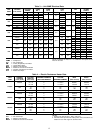
Unloader Settings (psig) Compressor No. 1 Only
Unloader No. 2
Loads 71.0 ± 1.5 —
Unloads 57.5 ± 2.5 —
Unloader No. 1
Loads 75.0 ± 1.5 75.5 ± 1.5
Unloads 62.5 ± 2.5 58.0 ± 2.5
Capacity Steps (%) 100,67,33
100,83,67
50,33,17
100,80,60
40,20
100,80,60
40,20
100,83,67
50,33,17
100,75,
50,25
CONDENSER FANS Propeller, Direct Drive
Motor Hp...Rpm...Frame (NEMA)
No. 1 1...1075...56 (Single phase)
No. 2 1...1140...56 (3 phase)
No. 3 ————1...1140...56 (3 phase)
Nominal Cfm 16,500 15,000 15,000 15,000 24,000 23,000
EVAPORATOR FANS* Centrifugal, Belt Drive
Number...Size (in.) 2...15 × 15 2...15 × 15 2...15 × 15 2...15 × 15 3...15 × 9 3...15 × 9
Cfm (Nominal) 6000 8000 10,000 10,000 12,000 12,000
Motor Hp...Rpm
Std 5...1725 7
1
⁄
2
...1725 10...1725 10...1725 15...1725 15...1725
Alt ————20...1725 20...1725
Fan Pulley
Outside Diameter (in.) 10.6 10.6 8.0 8.0 8.0 8.0
Bore (in.) 1
3
⁄
16
1
3
⁄
16
1
3
⁄
16
1
3
⁄
16
1
11
⁄
16
1
11
⁄
16
Fan Belt Number...Size
Std 1...3V630 1...3V630 2...3V560 2...3V560 2...3V630 2...3V630
Alt ————3...3V670 3...3V670
Motor Pulley Factory Installed
Outside Diameter (in.)
Std 5.3 6.0 5.0 5.0 5.0 5.0
Alt ————6.06.0
Bore (in.) 1
1
⁄
8
1
3
⁄
8
1
3
⁄
8
1
3
⁄
8
1
5
⁄
8
1
5
⁄
8
Resulting Fan Rpm
Std 880 995 1095 1095 1095 1095
Alt ————1320 1320
Shaft Center Line Distance (in.) 18 ± 2.5 18 ± 2.5 18 ± 2.5 18 ± 2.5 21 ± 2.5 21 ± 2.5
Maximum Fan Rpm 1300 1300 1300 1300 1550 1550
CONDENSER COOLING COIL Thermostatic Expansion Valve, Hot Gas Bypass
Face Area (sq ft) 6.8 6.8 6.8 6.8 10.2 10.2
Corrugated Fins/in. ...Rows 13...2 13...2 13...2 13...2 13...2 13...3
EVAPORATOR COILS (zone) Solenoid Valve and Capillary Tube for each
Number...Face Area (sq ft/ea) 8...2.12 8...2.12 10...2.12 10...2.12 12...2.01 12...2.01
Corrugated Fins/in. ...Rows 13...3 13...3 13...3 13...3 12...3 15...3
HEATING SECTION (48MA) One Heat Assembly in Each Zone Module
Rise Range 25 F to 55 F at 0.75 in. wg ESP
Input (1000 Btuh)
Total 432 432 540 540 648 648
Each Module 54 54 54 54 54 54
Bonnet Cap.† (1000 Btuh)
Total 324 324 405 405 486 486
Each Module 40.5 40.5 40.5 40.5 40.5 40.5
Burner Spud Qty...Size 2...38 2...38 2...38 2...38 2...38 2...38
OPTIONAL HEATING SECTION (50ME Electric)
Electric Heaters Nichrome, Open-Wire Resistance Element in Each Zone Module
Qty...Elements (each)** 8...2 or 3 8...2 or 3 10...2 or 3 10...2 or 3 12...2 or 3 12...2 or 3
OPTIONAL HEATING SECTION
(50ME Glycol Coil)
One Heating Coil in Each Zone Module
Maximum Allowable Inlet Temperature (F) 200
Maximum Allowable Flow, Each Coil (Gpm) 6
Solution Mixture 20% Glycol
Maximum Allowable Working Pressure (Psig) 30
Total Internal Volume (Gal) 2.61 2.61 3.15 3.15 3.76 3.76
PRESSURE SWITCHES
Low-Pressure (Psig)
Cutout 29±5
Cut-in 39±5
High-Pressure (Psig)
Cutout 400±5
Cut-in 300±5
Indoor Airflow Switch (AFS1)
Factory Setting (cfm) 6000 9000
Adjustment Range (cfm) 4000-6000 6000-9000
INDOOR AIR FILTERS
Standard Qty...Size (in.) 12...20 × 25 × 2
High Efficiency (optional)
Qty...Size (in.)
12...20 × 25 × 2 (36.5% Efficient)
OUTDOOR AIR FILTERS
Qty...Size (in.) 2...20 × 25 × 1 2...32 × 35 × 1
LEGEND
ESP — External Static Pressure
NEMA — National Electrical Manufacturers Association
*Standard unit shipped with standard motor, pulley, and belt(s); alternate unit shipped with alternate motor, pulley, and belt(s).
†The heating efficiency rating is a product thermal efficiency rating determined under continuous operating conditions independent of any installed system.
**See Field Power Supply Wiring section on page 10 and Table 4 for details.
6