


Unit has factory-installed gas shutoff valves. Install gas
shutoff valve external to unit if required by code (Fig. 8).
After piping is complete, pressurize gas line and check for
leaks with soap and water solution.
Do not use an open flame when checking for gas leaks.
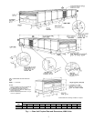
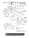
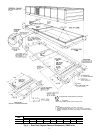
Optional Glycol Connections (50ME) — Each zone
module has its own glycol heating coil and 115-v solenoid
valve. Heating coils are connected in parallel to common sup-
ply and return manifolds. Supply manifolds are equipped with
bleed cocks. Supply and return connections are shown in
Fig. 2 and 5. Unit does not have internal pressure relief for
part-load operation. Maximum allowable system working pres-
sure is 30 psig. Unit ratings are based on 20% glycol solu-
tions. Install solution supply apparatus in accordance with
application requirements, and mix glycol solution percent-
age in accordance with glycol manufacturer’s recommenda-
tions. Freeze-up protection is not factory installed.
Field Power Supply Wiring — When installed, unit
must be electrically grounded in accordance with local codes
or, in the absence of local codes, with the National Electrical
Code (NEC).
Unit has a circuit breaker for each compressor, each fan
motor, and for each 50ME electric resistance heater assem-
bly (if unit is so equipped). If required by local code, pro-
vide an additional disconnect switch in accordance with code
being followed.
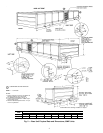
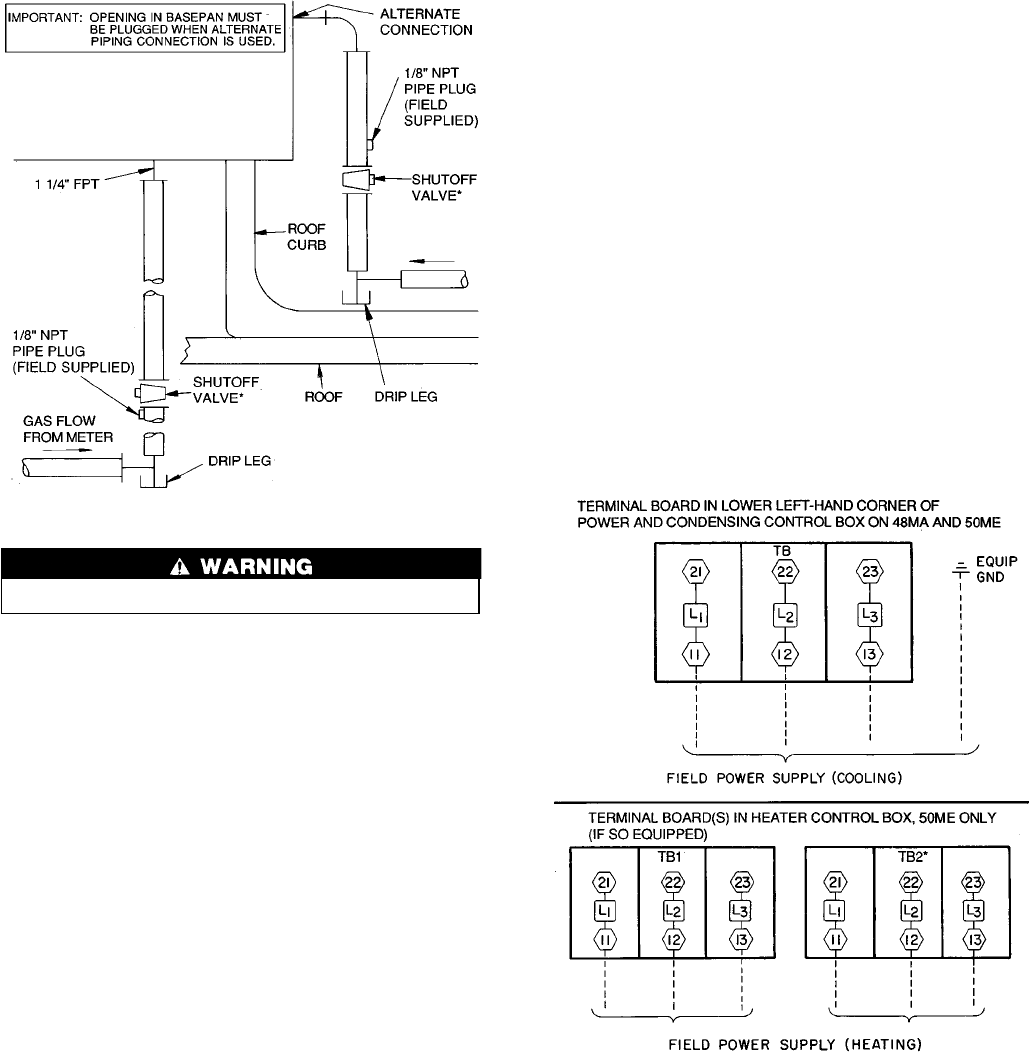
All units have a main power supply terminal board in the
power and condensing control box. The electric resistance
heater power supply terminal board(s) (if unit is so equipped)
on 50ME units is located in the heater control box at front
of unit. See Fig. 2, 5, and 9.
All terminal boards are suitable for use with copper or
aluminum wire.
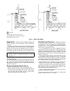
Connect electrical conduit (a threaded pipe nipple) shipped
with unit to threaded fitting in roof curb and bottom of main
power and condensing section control box. Route main power
wires through conduit to terminal board in box as shown on
unit label wiring diagram and in Fig. 9.
When installing 48MA,50ME040 units with optional 20-hp
motor, the electrical conduit interconnecting the curb and con-
trol box power wire openings will not accommodate alumi-
num wire of the size that may be required. If aluminum wire
cannot be accommodated, an external transition box and short
lengths of no. 300 kcmil, 75 C copper wire from the tran-
sition box to the unit main power connection are
recommended.
Voltage to compressor terminals during compressor op-
eration must be within voltage range indicated on unit name-
plate. Phases must be balanced within 2%.
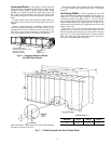
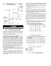
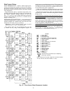
*Shutoff valve not used except where required by code.
Properly cap any gas connection not being used.
Fig. 8 — Suggested Gas Piping (48MA)
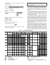
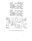
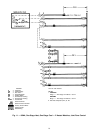
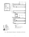
LEGEND
EQUIP — Equipment
GND — Ground
TB — Terminal Board
*208/230 v units only.
Fig. 9 — Field Power Supply Details
10