


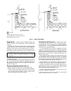
Use the following formula to determine the percent volt-
age imbalance.
% Voltage Imbalance:
max voltage deviation from average voltage
= 100 ×
average voltage
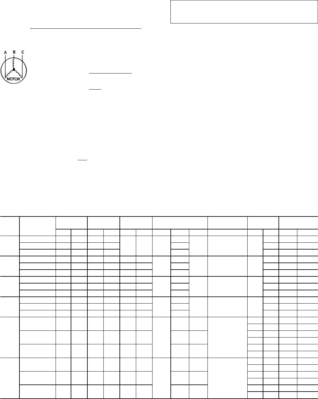
EXAMPLE: Supply voltage is 460-3-60.
AB = 452 v
BC = 464 v
AC = 455 v
452 + 464 + 455
Average Voltage =
3
1371
=
3
= 457
Determine maximum deviation from average voltage.
(AB) 457 − 452=5v
(BC) 464 − 457=7v
(AC) 457 − 455=2v
Maximum deviation is 7 v.
Determine percent voltage imbalance:
7
% Voltage Imbalance = 100 x
457
= 1.53%
This amount of phase imbalance is satisfactory as it is below
the maximum allowable 2%.
IMPORTANT: If the supply voltage phase imbalance
is more than 2%, contact your local electric utility com-
pany immediately.
Unit failure as a result of operation on improper line volt-
age or excessive phase imbalance constitutes abuse and may
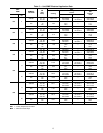
cause damage to electrical components. See Tables 2-5 for
unit, electric heater, and 50ME electrical application elec-
trical data.
Each 50ME electric heat unit is fitted with a heating lock-
out circuit (if equipped with optional heat). If any zone mod-
ule is operating on mechanical cooling (compressor is op-
erating), the heating element in each zone module is locked
out and cannot be energized.
On 50ME units, cooling power supply wires and electric
heater power supply wires (if applicable) must be sized ac-
cording to the cooling MCA (Minimum Circuit Amps) val-
ues and heating MCA values shown on unit nameplate and
in Tables 3-5. These wires may be powered by a common
power supply (i.e., a pull-box junction), if desired. The com-
mon power supply wires from the main power source to the
junction must be sized according to the common MCA val-
ues shown in Table 5.
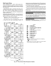
UNIT COMMON FEED MINIMUM CIRCUIT AMPS —
The unit common feed MCA is calculated on the basis of
either: the sum of the cooling MCA plus
1
⁄
2
heating MCA on
units with 2 heating elements per zone module (or
2
⁄
3
heat-
ing MCA on units with 3 heating elements per zone module)
or the sum of the evaporator fan motor full load amps, per
NEC, plus the full heating MCA, whichever is larger. Field
wiring must conform to NEC limitations for Type T wire.
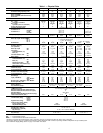
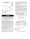
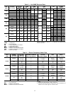
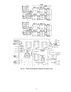
Table 2 — Unit 48MA Electrical Data
UNIT
48MA
Voltage
(3 Ph, 60 Hz)
VOLTAGE
RANGE
COMP
NO. 1
COMP
NO. 2
OFM
FLA
COMBUSTION
FAN MOTOR
IFM
POWER
SUPPLY
Min Max RLA LRA RLA LRA No. 1 No. 2 No. 3 FLA Hp FLA MCA MOCP
016
208/230 187 254 63.6 266
— — 6.2
6.6
— 1.8 5
16.2 109.6 125
460 414 508 28.6 120 3.0 6.6 49.8 60
575 518 632 22.8 96 2.4 5.6 39.8 45
024
208/230 187 254 44.4 170 44.4 170
6.2
6.6
— 1.8 7.5
24.2 137.5 150
460 414 508 19.9 77 19.9 77 3.0 11.0 62.2 70
575 518 632 15.7 62 15.7 62 2.4 9.0 49.4 60
028
208/230 187 254 63.6 266 44.4 170
6.2
6.6
— 1.8 10
30.8 168.1 200
460 414 508 28.6 120 19.9 77 3.0 13.0 76.1 90
575 518 632 22.8 96 15.7 62 2.4 10.5 60.4 70
030
208/230 187 254 63.6 266 63.6 266
6.2
6.6
— 1.8 10
30.8 187.3 200
460 414 508 28.6 120 28.6 120 3.0 13.0 84.5 100
575 518 632 22.8 96 22.8 96 2.4 10.5 67.5 90
034
208/230 187 254 63.6 266 63.6 266
6.2
6.6 6.6
1.8
15 46.2 210.8 225
20 61.0 224.6 250
460 414 508 28.6 120 28.6 120 3.0 3.0
15 21.0 94.5 100
20 26.6 100.5 125
575 518 632 22.8 96 22.8 96 2.4 2.4
15 16.0 75.6 90
20 21.3 80.6 100
040
208/230 187 254 80.0 345 80.0 345
6.2
6.6 6.6
1.8
15 46.2 247.7 300
20 61.0 261.5 300
460 414 508 38.5 150 38.5 150 3.0 3.0
15 21.0 116.7 150
20 27.0 122.7 150
575 518 632 31.4 120 31.4 120 2.4 2.4
15 16.0 95 125
20 21.3 100 125
LEGEND
COMP — Compressor
FLA — Full Load Amps
IFM — Indoor (Evaporator) Fan Motor
LRA — Locked Rotor Amps
MCA — Minimum Circuit Amps
MOCP — Maximum Overcurrent Protection
OFM — Outdoor (Condenser) Fan Motor
RLA — Rated Load Amps
NOTES:
1. Combustion air fan is a 115-1-60 motor on all units.
2. Condenser fan motor no. 1 is a 208/230-1-60 speed control motor
on all units.
11