


PULLEY REMOVAL
1. Shut off unit power.
2. Loosen fan motor mounting plate and remove belt.
3. Loosen pulley setscrew.
4. Slide pulley off shaft.
Reverse steps 1-4 to install new pulley.
PULLEYALIGNMENT — Loosen fan pulley setscrews and
slide fan pulley along fan shaft for parallel alignment. Make
angular alignment by loosening motor from mounting plate.
BELT TENSION ADJUSTMENT — Loosen fan motor pivot
bolts. Pull back motor mounting plate to proper belt tension
(approximately
3
⁄
4
-in. deflection with one finger) and tighten
motor pivot bolts.
LUBRICATION — Evaporator-fan shaft and motor bear-
ings require annual lubrication after 3 to 5 years of continu-
ous operation as follows:
Fan Shaft Bearings — Automotive-type grease fittings are
factory supplied. Apply a medium-duty, lithium-based grease
to fittings while rotating shaft.
Fan Motor Bearings — Remove plugs and install automotive-
type grease fittings. Use a suitable motor bearing grease per
motor manufacturer’s recommendations.
Forced-Draft Blower (48MA)
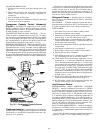
LUBRICATION — Add 2or3dropsof a good grade of
no. 20 SAE (Society of Automotive Engineers) motor oil at
each oil cup on the motor once a year.
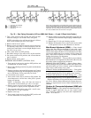
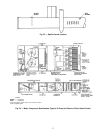
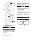
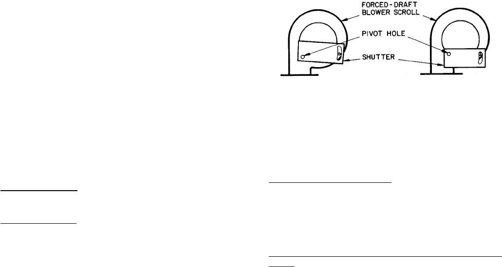
AIR SHUTTER ADJUSTMENT — The air shutter is held
in position on the blower inlet by a wing nut. Loosen wing
nut and reposition shutter until correct pressure is achieved.
Combustion chamber air pressure is to be measured through
drain connection below heat exchangers. Correct pressures
are 0.10 ± 0.01 in. wg for units 48MA016,024,034, and 040;
0.14 ± 0.01 for units 48MA028 and 030. Figure 39 shows
correct shutter position. Note pivot hole location.
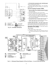
Zone Module Transformers — When replacing these
transformers, be sure to connect wires on correct terminals
to maintain correct polarity. See base unit label diagram on
the unit for connections.
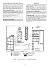
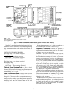
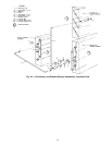
Optional Economizer — See Fig. 40.
THERMOSTAT SETTINGS — Set economizer outdoor air
thermostat (ECT) at a temperature which will provide cool-
ing with outdoor air only. This setting, when achieved, will
lock out the compressor(s). A 45 F setting is suggested.
Set mixed-air thermostat (MAT) as desired to provide mixed
air of the correct temperature. This setting cannot be lower
than the ECT setting. A 58 F setting is suggested.
DAMPER POSITION — When outdoor-air damper is fully
open, the return-air damper will be fully closed and vice versa.
OPERATION
Heating or Compressor Cooling — Dampers will assume the
ventilation position indicated by the ventilation control knob.
If a remote control center is used, DAY/NIGHT switch must
be at the DAY position.
If terminals in unit control box labeled SHORT TO CLOSE
DAMPERS are shorted or if DAY/NIGHT switch is set at
NIGHT position, outdoor-air damper will close.
Intermediate Season (Free Cooling Using Optional Econo-
mizer) — If outdoor-air temperature drops below econo-
mizer outdoor-air thermostat (ECT) setting, the compressor(s)
will remain off. The dampers will modulate to maintain the
mixed-air thermostat (MAT) setting. If the outdoor air tem-
perature rises above the ECT setting, the unit will operate as
described in Heating or Compressor Cooling section above.
Optional Exhaust Damper — See Fig. 34 and 35.
When unit is on economizer cycle (free cooling) and an ex-
haust damper is part of the unit, the exhaust relay is ener-
gized. The fan motor controls the Motormaster head pres-
sure control and the fan cycling pressure switches are bypassed
so that condenser fans operate at full speed as follows:
• Fan no. 1 and 2 on units 48MA/50ME016-030
• Fan no. 2 and 3 on units 48MA/50ME034,040
When the return air damper is 25% closed, the exhaust
damper begins to open. The condenser fans pull indoor re-
turn air through the open exhaust damper and discharge it to
the outdoors.
Replacement Parts — A complete list of replacement
parts may be obtained from any Carrier distributor upon
request.
48MA016 AND 024 48MA028-040
Fig. 39 — Forced-Draft Blower
Shutter Position
42