


The heating thermostat energizes a 115-v solenoid by means
of a gas valve relay and the pilot lights. The main burner
comes on after the pilot is proven.
The safety switches (airflow switches 1 and 2, pilot flame
sensor, door switch, and limit switches) are in series with
the gas valve.
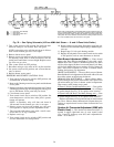
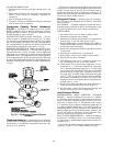
Gas Heat Lighting Procedure (48MA)
1. Purge gas supply line of air. Make sure unit main manual
and zone module gas valves have been off for 5 minutes
before proceeding.
2. Set each zone thermostat to the lowest setting.
3. Turn zone module and main manual gas valves to ON
position, and secure door of burner compartment.
4. Turn on unit main power supply. Set control circuit serv-
ice switch in condensing control box at ON position. Evapo-
rator fan will be energized.
5. Set zone thermostat to call for heat. Pilot will light. The
main burner will come on after the pilot is proven.
NOTE: A time-delay relay will shut unit down in 180 sec-
onds if main manual gas valve is not open.
TO SHUT OFF GAS HEAT — Set control circuit service
switch at OFF position. Shut off unit power supply only if
necessary. Remove heating controls compartment access door.
Shut off main manual gas valves and pilot manual gas valves.
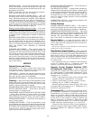
Intermittent Pilots (48MA) — Pilot flame should be
approximately 1 to 1
1
⁄
2
in. high.
ADJUSTMENT
1. Turn system switch to OFF position.
2. If intending to adjust every zone, disconnect main gas
valve wires from terminal W on pilot switches in each
zone.
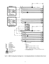
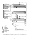
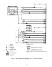
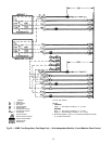
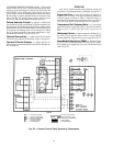
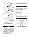
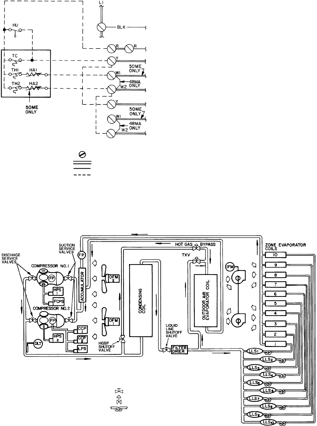
LEGEND
HA — Heat Anticipator
HU — Humidistat
TC — Thermostat, Cooling
TH — Thermostat, Heating
Screw Terminal
Printed Circuit
Factory Control Wires
Field Wiring
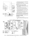
Fig. 30 — Humidistat Connections
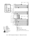
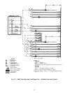
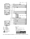
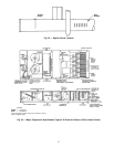
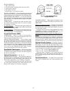
LEGEND
CCP — Capacity Control Pressure Switch
DLT — Discharge Line Thermostat
FCPS — Fan Cycling Pressure Switch
FP — Fusible Plug
HGBP — Hot Gas Bypass
HPS — High-Pressure Switch
IFM — Indoor (Evaporator) Fan Motor
LLS — Liquid Line Solenoid
LPS — Low-Pressure Switch
OFM — Outdoor (Condenser) Fan Motor
TXV — Thermostatic Expansion Valve
Hand Valve
Auto. Valve
Capilliary
Fig. 31 — Refrigerant Piping Schematic (10-Zone Unit Shown — 8- and 12-Zone Units Similar)
35