


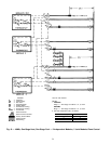
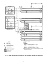
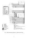
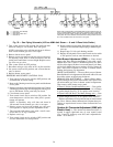
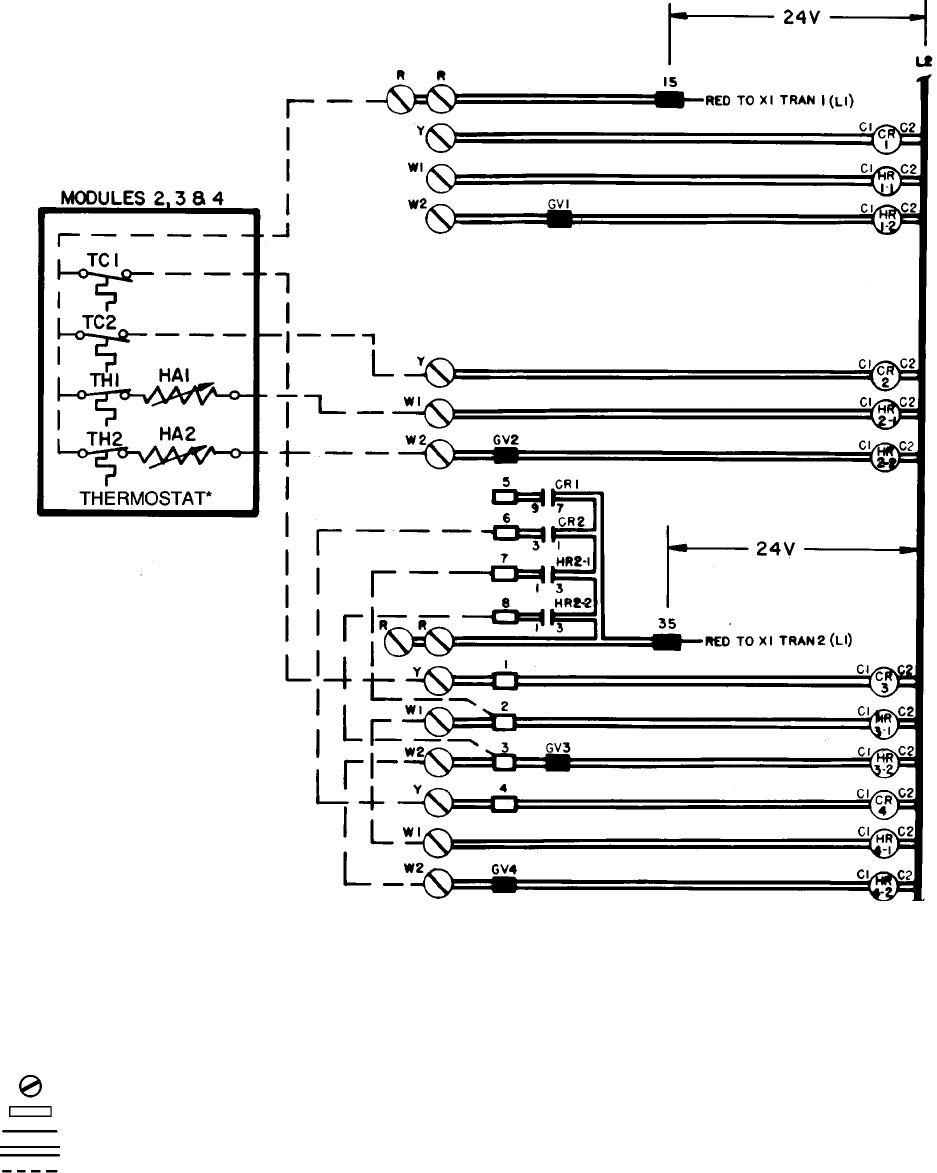
LEGEND
C—Contactor
CR — Control Relay
GV — Gas Valve
HA — Heat Anticipator
HR — Heating Relay
TC — Thermostat, Cooling
TH — Thermostat, Heating
TRAN — Transformer
Screw Terminal
Quick-Connect Terminal
Factory Control Wires
Printed Circuit
Field Wiring
*One for each module.
NOTES:
1. COOLING
Stage 1 — Module 3
Stage 2 — Module 2 and 4
If thermostat wires are interchanged, the reverse may be
obtained.
HEATING
Stage 1 — First stage of modules 2, 3, and 4
Stage 2 — Second stage of modules 2, 3, and 4
2. Set heat anticipator 1 (HA1) at .13, and set heat anticipator 2 (HA2)
at .57.
Fig. 27 — 50ME; Two-Stage Heat, Two-Stage Cool — 3 Module Joint Zone Control
32