


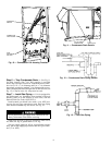
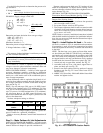
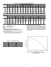
Step 8 — Make Electrical Connections
FIELD POWER SUPPLY — Unit is factory wired for volt-
age shown on unit nameplate.
When installing units, provide a disconnect per NEC
(National Electrical Code) of adequate size (Table 2).
All field wiring must comply with NEC and local
requirements.
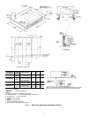
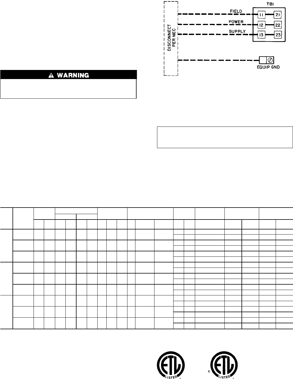
Route power and ground lines through control box end
panel or unit basepan (see Fig. 4 and 5) to connections as
shown on unit wiring diagram and Fig. 14.
The unit must be electrically grounded in accordance
with local codes and NEC ANSI/NFPA 70 (National Fire
Protection Association).
Field wiring must conform to temperature limitations for
type ‘‘T’’ wire. All field wiring must comply with NEC and
local requirements.
Transformer no. 1 is wired for 230-v unit. If 208/230-v
unit is to be run with 208-v power supply, the transformer
must be rewired as follows:
1. Remove cap from red (208 v) wire.
2. Remove cap from orange (230 v) spliced wire.
3. Replace orange wire with red wire.
4. Recap both wires.
IMPORTANT: BE CERTAIN UNUSED WIRES
ARE CAPPED. Failure to do so may damage the
transformers.
Operating voltage to compressor must be within voltage
range indicated on unit nameplate. On 3-phase units, volt-
ages between phases must be balanced within 2%.
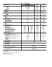
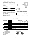
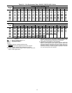
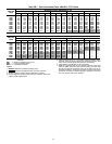
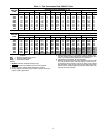
Table 2 — Electrical Data
UNIT
48HJ
NOMINAL
VOLTAGE
(3 Ph,
60 Hz)
VOLTAGE
RANGE
COMPRESSOR
OFM IFM
POWER
EXHAUST
COMBUSTION
FAN MOTOR
POWER SUPPLY
DISCONNECT
SIZE
No. 1 No. 2
Min Max RLA LRA RLA LRA Qty
FLA
(ea)
LRA
(ea)
Hp FLA LRA FLA LRA FLA MCA MOCP* FLA LRA
015
208/230 187 254 39.7 228 — — 3 1.7 3.8 3.7 10.5/10.5 84.5/84.5
— — 0.57 65/65 100/100 64/64 324/324
4.6 18.8 0.57 70/70 100/100 70/70 343/343
460 414 508 19.9 114 — — 3 0.8 1.9 3.7 4.8 42.3
— — 0.30 32 50 32 162
2.3 6.0 0.30 34 50 34 168
575 518 632 16.0 91 — — 3 0.75 1.5 3 3.9 23.4
— — 0.57 26 40 26 119
2.1 4.8 0.57 28 40 29 124
017
208/230 187 254 28.2 160 28.2 160 3 1.7 24.8 5 15.8/15.8 105/91
— — 0.57 84/84 110/100 90/90 499/485
4.6 18.8 0.57 89/89 110/110 95/95 518/504
460 414 508 14.1 80 14.1 80 3 0.8 10.8 5 7.9 46
— — 0.30 42 50 45 238
2.3 6.0 0.30 44 50 47 244
575 518 632 11.3 64 11.3 64 3 0.75 8.4 5 6.0 37
— — 0.57 34 40 36 190
2.1 4.8 0.57 36 45 39 195
025
208/230 187 254 35.6 198 35.6 198 2 5.5 24.8 10 28.0/28.0 193/168
— — 0.57 119/119 150/150 127/127 639/614
4.6 18.8 0.57 124/124 150/150 133/133 657/632
460 414 508 17.8 99 17.8 99 2 2.8 10.8 10 14.6 84
— — 0.30 60 70 65 304
2.3 6.0 0.30 63 80 67 310
575 518 632 14.3 79 14.3 79 2 3.4 8.4 10 13.0 66
— — 0.57 52 60 56 241
2.1 4.8 0.57 54 60 59 246
LEGEND
FLA — Full Load Amps
HACR — Heating,Air Conditioning and Refrigeration
IFM — Indoor (Evaporator) Fan Motor
LRA — Locked Rotor Amps
MCA — Minimum Circuit Amps
MOCP — Maximum Overcurrent Protection
NEC — National Electrical Code
OFM — Outdoor (Condenser) Fan Motor
RLA — Rated Load Amps
*This is the maximum size permissible; smaller fuse size may be used where
conditions permit.
NOTES: In compliance with NEC requirements for multimotor and combina-
tion load equipment (refer to NEC Articles 430 and 440), the overcurrent pro-
tective device for the unit shall be fuse or HACR breaker. TheCanadian units
may be fuse or circuit breaker.
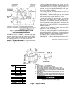
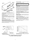
LEGEND
EQUIP — Equipment
GND — Ground
NEC — National Electrical Code
TB — Terminal Board
NOTE: Maximum wire size for TB1 is 2/0.
Fig. 14 — Field Power Wiring Connections
9