


Main Burners — For most applications, main burners
are factory set and should require no adjustment. However,
if burner adjustment is necessary:
1. Perform pilot adjustment.
2. Turn gas valve to ON position. Allow unit to operate at
least 15 minutes with burner access panel in place.
3. Remove access panel.
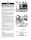
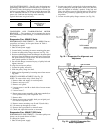
4. Loosen primary air shutter (Fig. 37) and adjust to a mini-
mum opening of
5
⁄
8
inch.
5. Retighten primary air shutter and reinstall access panel.
To check ignition of main burners and fan switch opera-
tion, move thermostat dial above and below room tempera-
ture several times,pausing at least one minute between cycles.
MAIN BURNER REMOVAL
1. Shut off (field-supplied) manual main gas valve.
2. Shut off power to unit.
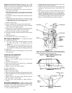
3. Remove unit control box/gas valve access panel, burner
section access panel, and center post (Fig. 4 and 5).
4. Disconnect pilot ignitor and pilot proving sensor leads at
ICP, rollout switch leads at switch, and pilot tube gas con-
nection(s) at the pilot orifice.
5. Disconnect gas connection(s) from between gas valve(s)
and main burners.
6. Remove 2 screws securing burner assembly to base unit.
7. Slide burner assembly out of unit.
Filter Drier — Replace whenever refrigerant system is
exposed to atmosphere.
Protective Devices
COMPRESSOR PROTECTION
Overcurrent — Each compressor has one manual reset, cali-
brated trip, magnetic circuit breaker. Do not bypass connec-
tions or increase the size of thecircuit breaker to correcttrouble.
Determine the causeand correct it before resetting the breaker.
Overtemperature — Each compressor has an internal pro-
tector to protect it against excessively high discharge gas
temperatures.
Crankcase Heater— Each compressor has a 125-watt crank-
case heater to prevent absorption of liquid refrigerant by oil
in the crankcase when the compressor is idle. Since power
for the crankcase heaters is drawn from the unit incoming
power, main unit power must be on for the heaters to be
energized.
IMPORTANT: After a prolonged shutdown or serv-
ice job, energize the crankcase heaters for 24 hours
before starting the compressors.
Compressor Lockout — If any of the safeties (high-, low-
pressure, freeze protection thermostat, compressor internal
thermostat) trip, or if there is loss of power to the compres-
sors, the cooling lockout (CLO) will lock the compressors
off. To reset, manually move the thermostat setting.
EVAPORATOR-FAN MOTOR PROTECTION —Amanual
reset, calibrated trip, magnetic circuit breaker protects against
overcurrent. Do not bypass connections or increase the size
of the breaker to correct trouble. Determine the cause and
correct it before resetting the breaker.
CONDENSER-FAN MOTOR PROTECTION — Each
condenser-fan motor is internally protected against
overtemperature.
HIGH- AND LOW-PRESSURE SWITCHES — If either
switch trips, or if the compressor overtemperature switch ac-
tivates, that refrigerant circuit will be automatically locked
out by the CLO. To reset, manually move the thermostat
setting.
FREEZE PROTECTION THERMOSTAT (FPT) — An
FPT is located on the evaporator coil. It detects frost
build-up and turns off the compressor, allowing the coil to
clear. Once the frost has melted, the compressor can be
reenergized by resetting the CLO from the thermostat.
Relief Devices — All units have relief devices to pro-
tect against damagefrom excessive pressures (i.e., fire). These
devices protect the high and low side.
Control Circuit, 24-V — This control circuit is pro-
tected against overcurrent by a3.2-amp circuit breaker. Breaker
can be reset. If it trips, determine cause of trouble before
resetting.
Replacement Parts — A complete list of replacement
parts may be obtained from any Carrier distributor upon
request.
23