


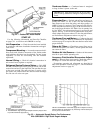
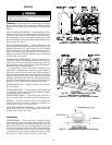
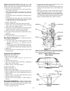
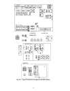
SERVICE AND REPLACEMENT (See Fig. 30) — The
48HJ017,025 units use a fan motor mounting system that
features a slide-out motor mounting plate.To replace or serv-
ice the motor, slide out the bracket.
1. Remove the evaporator-fan access panel and the heat-
ing control access panel.
2. Remove the center post (located between the evaporator
fan and heating control access panels) and all screws
securing it.
3. Loosen nuts on the two carriage bolts inthe motor mount-
ing base.
4. Using jacking bolt under motor base, raise motor to top
of slide and remove belt. Secure motor in this position
by tightening the nuts on the carriage bolts.
5. Remove the belt drive.
6. Remove jacking bolt and tapped jacking bolt plate.
7. Remove the 2 screws that secure the motor mounting
plate to the motor support channel.
8. Remove the 3 screws from the end of the motor support
channel that interfere with the motor slide path.
9. Slide out the motor and motor mounting plate.
10. Disconnect wiring connections and remove the 4 mount-
ing bolts.
11. Remove the motor.
12. To install the new motor, reverse Steps 1-11.
Belt Tension Adjustment — To adjust belt tension:
1. Loosen fan motor bolts.
2. a. 015 Units: Move motor mounting plate up or down
for proper belt tension (
1
⁄
2
in. deflection with one
finger).
b. 017,025 Units: Turn motor jacking bolt to move mo-
tor mounting plate up or down for proper belt tension
(
3
⁄
8
in. deflection at midspan withone finger [9lb force]).
3. Tighten nuts.
4. Adjust bolts and nut on mounting plate to secure motor
in fixed position.
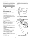
Condenser-Fan Adjustment
48HJ015,017 UNITS (Fig. 31)
1. Shut off unit power supply.
2. Remove access panel(s) closest to the fan to be
adjusted.
3. Loosen fan hub setscrews.
4. Adjust the fan height on the shaft using a straightedge
placed across the fan orifice.
5. Tighten setscrews and replace panel(s).
6. Turn on unit power.
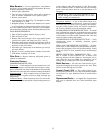
48HJ025 UNITS (Fig. 32)
1. Shut off unit power supply.
2. Remove fan top-grilleassembly andloosen fanhub screws.
3. Adjust fan height onunit, using astraightedge placedacross
the fan orifice.
4. Tighten setscrews and replace rubber hubcap to prevent
hub from rusting to motor shaft.
5. Fill hub recess with permagum if rubber hubcap is
missing.
Economizer Adjustment — Refer to Tables 8 and 9
for economizer checkout procedures. Make certain theoutdoor-
air damper is fully closed and the return-air damper is fully
open before completing the following steps:
1. Turn on power to the unit.
2. Turn the thermostat fan switch to the ON position. The
damper will go to the vent position.
3. Adjust the vent position with the minimum position ad-
justment on the economizer motor control module. See
Fig. 18.
4. Set the system selector switch to COOL position and set
the cooling temperature selector to its lowest setting.
NOTE: The Cooling mode may also be simulated by
removing the thermostat wires from terminals Y1 and
Y2 and installing a jumper between terminals R andY1.
Refer to unit label diagram for terminal locations.
NOTE:A3
1
⁄
2
-in. bolt and threaded plate are included in the installer’s
packet. They can be added to the motor support channel below the
motor mounting plate to aid in raising the motor.
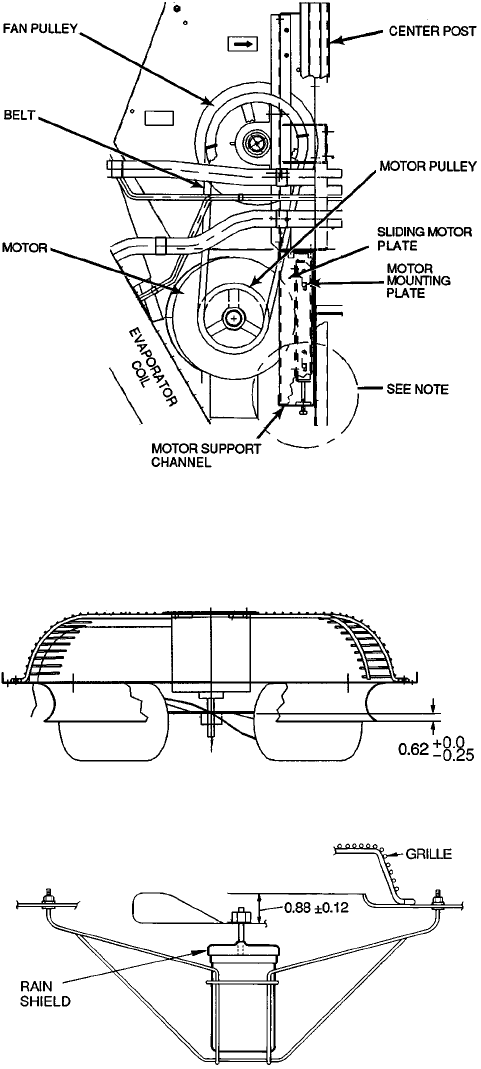
Fig. 30 — 48HJ017,025 Evaporator-Fan
Motor Section
Fig. 31 — Condenser Fan Adjustment,
48HJ015,017
Fig. 32 — Condenser-Fan Adjustment,
48HJ025
20