31
Step 3 — Install Light Commercial Thermidistat
1. Turn off all power to equipment. Tag disconnect.
2. If an existing thermostat is being replaced:
a. Remove existing thermostat from wall.
b. Disconnect wires from existing thermostat, one at
a time.
c. As each wire is disconnected, record wire color
and terminal marking.
d. New or additional wire may be needed to accommo-
date added humidity outputs transformer common.
e. Discard or recycle old thermostat.
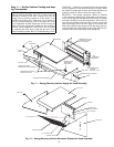
3. Route wires through large hole in rear plastic. Level rear
plastic (separated from front plastic in Step 2 — Set DIP
Switches, on page 30). Level rear plastic against wall (for
aesthetic value only — Light Commercial Thermidistat
need not be leveled for proper operation) and mark wall
through 2 mounting holes.
4. Drill two
3
/
16
-in. mounting holes in wall where marked.
5. Secure rear plastic to wall with 2 screws and anchors
provided. Additional mounting holes are available for
more secure mounting if needed. Make sure all wires
extend through hole in mounting base.
6. Adjust length and routing of each wire to reach proper
connector block and terminal on mounting base with
1
/
4
-in. extra length. Strip only
1
/
4
in. of insulation from
each wire to prevent adjacent wires from shorting togeth-
er when connected.
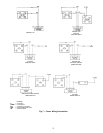
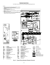
7. Match and connect equipment wires to proper terminals
of each connector block. Remember R and C must be
connected for proper operation (see Fig. 14).
8. Push any excess wire into wall and against rear plastic.
Seal hole in wall to prevent air leaks. Leaks can affect
operation.
9. Reattach Light Commercial Thermidistat body to mount-
ing base by first reattaching hinge.
10. Close Light Commercial Thermidistat assembly, making
sure pins on back of circuit board align with sockets in
connector.
11. Turn on power to equipment.
On power up, all display segments will light for 2 seconds.
For the next 8 seconds, a 2-digit code appears on LED display
that identifies Light Commercial Thermidistat configuration:
CP — Commercial Product
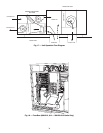
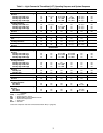
Step 4 — Set Light Commercial Thermidistat
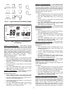
Configuration (Fig. 15 and 16) —
Configuration op-
tions, like DIP switch settings, are intended to be selected at
installation and normally are not modified by the owner. These
options must be made as part of the installation. A special
procedure allows entry into the Configuration mode. While in
configuration mode, up to 10 selections can be made. A
description of each selection and how to use the Configuration
mode are as follows:
CONFIGURATION OPTIONS — SUMMARY
Option 1 — Anticipator adjustment
Option 2 — Clean filter timer adjustment
Option 3 — English/Metric selection
Option 4 — Fan (G) ON with W selection
Option 9 — Holiday heat set point
Option 10 — Holiday cool set point
Option 11 — Holiday humidity set point
Option 13 — Room temperature offset adjustment
Option 14 — Heat cool deadband adjustment
Option 21 — Keyboard lock
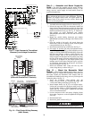
TO ENTER CONFIGURATION MODE — Press and hold
FAN button for approximately 10 seconds until COOL set
point display indicates a flashing “01”. The Light Commercial
Thermidistat is now in Configuration mode. It will automati-
cally exit this mode if no button is pressed for 3 minutes. Press-
ing HOLD End button will exit the Configuration mode
immediately.
WHILE IN CONFIGURATION MODE — The upper small
(COOL set point) display indicates selected option number and
large display indicates selection made within that option. One of
these will be flashing. The up and down set point buttons are
used both to move between available options and to make selec-
tion for each option. When option number (small display) is
flashing, the up and down set point buttons allows for scrolling
through options moving between available option numbers.
After desired option number has been selected, press SET
TIME/TEMP button once. The large display will now flash,
indicating that up and down set point buttons now control avail-
able choices within that option. Each press of SET TIME/
TEMP button switches between available option (small display)
and available selections within each option (large display).
Option 1 — Anticipator Adjustment
— This adjustment
controls sensitivity and cycle rate of Light Commercial Ther-
midistat. Higher numbers decrease sensitivity and slow cycle
rate. Lower numbers increase sensitivity and cycle rate. Antici-
pator values can range from 1 to 9. Factory default is 3. This
default selection provides optimum performance in nearly all
installations. Try it first; do not change setting unless there is
evidence of need to do so.
Unlike conventional anticipators, this setting is not deter-
mined by current draw. There is no need to measure, know, or
compensate for current draw. There is also no droop with this
Light Commercial Thermidistat. Regardless of setting and
number of stages, both heating and cooling will control to their
respective set points.
TO ADJUST:
1. Enter Configuration mode. The upper small (COOL set
point) display will be flashing 01. If not, use up and down
set point buttons to move it to 01.
2. Press SET TIME/TEMP button once to flash current
selection of 1, 2, 3, 4, 5, 6, 7, 8, or 9 on large display.
Factory default is 3.
3. Use up and down set point buttons to move to desired
anticipator setting.
4. Press SET TIME/TEMP button again to flash small
upper display for selection of another option, or press
HOLD End to exit Configuration mode.
Before installing Light Commercial Thermidistat, turn off
all power to Weathermaster® COBRA units. There may be
more than one power disconnect. Electrical shock
can cause personal injury or death. Install lockout tags on
disconnects.
Mercury is a hazardous waste and MUST be disposed of
properly.
Improper wiring or installation may damage Light
Commercial Thermidistat. Check to make sure wiring is
correct before proceeding with installation or turning on
power. Refer to wiring schematic in the Troubleshooting
section of this manual.


