


Manufacturer reserves the right to discontinue, or change at any time, specifications or designs without notice and without incurring obligations.
PC 111 Catalog No. 534-80122 Printed in U.S.A. Form 48/50HJ,62AQ-2SIS Pg 1 9-02 Replaces: 48/50HJ,62AQ-1SIS
Book 1144
Tab 1a1b6a6b
Installation, Start-Up,
and Service Supplement
CONTENTS
Page
SAFETY CONSIDERATIONS
. . . . . . . . . . . . . . . . . . . . . . 1
GENERAL
. . . . . . . . . . . . . . . . . . . . . . . . . . . . . . . . . . . . . . . . 1
INSTALLATION
. . . . . . . . . . . . . . . . . . . . . . . . . . . . . . . . 2-29
Step 1 — Inspect Shipment
. . . . . . . . . . . . . . . . . . . . . . 2
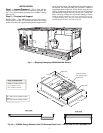
Step 2 — Provide Unit Support
. . . . . . . . . . . . . . . . . . . 2
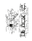
•ROOF CURB
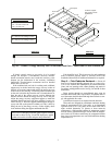
Step 3 — Field Fabricate Ductwork
. . . . . . . . . . . . . . . 3
Step 4 — Rig and Place Unit
. . . . . . . . . . . . . . . . . . . . . 6
• POSITIONING
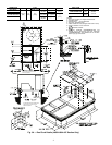
Step 5 — Install Flue Hood (48HJ Only)
. . . . . . . . . 11
Step 6 — Install Gas Piping (48HJ Only)
. . . . . . . . . 11
Step 7 — Install External Trap for Condensate
Drain
. . . . . . . . . . . . . . . . . . . . . . . . . . . . . . . . . . . . . . . . . . 11
Step 8 — Make Electrical Connections
. . . . . . . . . . 11
• FIELD POWER SUPPLY
• FACTORY-SUPPLIED NON-FUSED
DISCONNECT
• FIELD CONTROL WIRING
• HEAT ANTICIPATOR SETTINGS
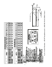
Step 9 — Assemble and Mount
Supply-Air Hood
. . . . . . . . . . . . . . . . . . . . . . . . . . . . . . 28
Step 10 — Mount the Barometric Relief Damper
. . 28
Step 11 — Set the Outdoor Cooling and
Heating Thermostats
. . . . . . . . . . . . . . . . . . . . . . . . . . 29
LIGHT COMMERCIAL THERMIDISTAT
ACCESSORY
. . . . . . . . . . . . . . . . . . . . . . . . . . . . . . . 30-34
General
. . . . . . . . . . . . . . . . . . . . . . . . . . . . . . . . . . . . . . . . . . 30
Power
. . . . . . . . . . . . . . . . . . . . . . . . . . . . . . . . . . . . . . . . . . . 30
Dehumidification Equipment and Connections
. . . 30
Step 1 — Select Light Commercial
Thermidistat Location
. . . . . . . . . . . . . . . . . . . . . . . . . 30
Step 2 — Set DIP Switches
. . . . . . . . . . . . . . . . . . . . . . . 30
Step 3 — Install Light Commercial Thermidistat
. . 31
Step 4 — Set Light Commercial Thermidistat
Configuration
. . . . . . . . . . . . . . . . . . . . . . . . . . . . . . . . . . 31
Step 5 — Conduct Light Commercial
Thermidistat Start-Up and Checkout
. . . . . . . . . . . 33
Step 6 — Make Final Settings
. . . . . . . . . . . . . . . . . . . . 34
OPERATIONAL INFORMATION
. . . . . . . . . . . . . . . . . . 34
PRE-START-UP
. . . . . . . . . . . . . . . . . . . . . . . . . . . . . . . . . . 35
START-UP
. . . . . . . . . . . . . . . . . . . . . . . . . . . . . . . . . . . . . . . 35
SERVICE
. . . . . . . . . . . . . . . . . . . . . . . . . . . . . . . . . . . . . 35-37
TROUBLESHOOTING
. . . . . . . . . . . . . . . . . . . . . . . . . 38-41
ROOFTOP UNIT AND ENERGY$RECYCLER2
START-UP CHECKLIST
. . . . . . . . . . . . . . . . CL-1, CL-2
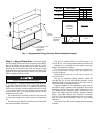
SAFETY CONSIDERATIONS
Installation and servicing of air-conditioning equipment can
be hazardous due to system pressure and electrical compo-
nents. Only trained and qualified service personnel should
install, repair, or service air-conditioning equipment.
Untrained personnel can perform basic maintenance func-
tions of cleaning coils and filters and replacing filters. All other
operations should be performed by trained service personnel.
When working on air-conditioning equipment, observe precau-
tions in the literature, tags and labels attached to the unit, and
other safety precautions that apply.
Verify that the power source supplied to the unit matches
the voltages and amperages listed on the unit rating plate.
Follow all safety codes. Wear safety glasses and work
gloves. Use quenching cloth for unbrazing operations. Have
fire extinguishers available for all brazing operations.
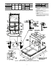
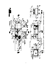
GENERAL
Carrier’s factory-installed optional COBRA Energy Recov-
ery units precondition ventilation air for the rooftop unit during
winter and summer operation and recover energy from the
building exhaust air. These units are designed to satisfy the
higher ventilation requirements and other building codes while
minimizing energy costs.
Factory installation of the energy recovery section provides
the benefit of reduced field-installation time, single point pow-
er connections, and the assurance of a factory test for the com-
plete COBRA Energy Recovery unit. The energy recovery sec-
tion requires less maintenance than other energy recovery
systems and can be serviced by any qualified refrigeration
technician.
NOTE: Because of the location of the energy recovery section,
the unit nameplate has been moved to the opposite end of the
rooftop section, on the upper, right-hand part of the panel.
IMPORTANT: This is a supplemental instruction for the
48/50HJ and the 62AQ Installation, Start-Up and Service
Instructions. It is not intended to take the place of either
instruction or to be a complete piece in itself.
Disconnect gas piping from unit when leak
testing at pressure greater than
1
/
2
psig. Pres-
sures greater than
1
/
2
psig will cause gas
valve damage resulting in hazardous condi-
tion. If gas valve is subjected to pressure
greater than
1
/
2
psig, it must be replaced
before use. When pressure testing field-
supplied gas piping at pressures of
1
/
2
psig or
less, a unit connected to such piping must be
isolated by manually closing the gas valve.
Before performing service or maintenance operations on
unit, turn off main power switch to unit and install a lock-
out tag. Electrical shock could cause personal injury.
COBRA™ Energy Recovery Units
48/50HJ004-014 with 62AQ060-300
Single-Package Rooftop Units
with Energy Recovery Capability