Manufacturer reserves the right to discontinue, or change at any time, specifications or designs without notice and without incurring obligations.
New Pg 40 Catalog No. 524-236 Printed in U.S.A. Form 42B-1PD
Replaces: 42BHC-1PD
Book 3
Tab 7a
Carrier Corporation • Syracuse, New York 13221 9-05A 9-05
Book 4
Tab 4FC4
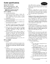
2) One-in. pleated, (2) 1-in. throwaway or
2-in pleated MERV 11 filters with 2-in.
pre-filter shall be installed as indicated
on the equipment schedule.
c. Insulation:
1) Units shall be equipped with 1-in. thick
Tuf-Skin™ II insulation (standard).
2) Units are available with ¾-in. closed
cell, 1-in. Tuf-Skin Rx™ edge sealed,
or 1-in. foil-faced insulation.
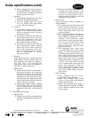
d. Controls:
1) Unit shall be equipped with 24-v trans-
former, motor contactor and terminal
strip for connection to field or factory
provided controller.
2) Unit shall be equipped with interlock-
ing door-disconnect switch, touch-type
fusing, 24-v transformer, motor con-
tactor and terminal strip for connec-
tion to field provided controller.
3) Unit shall be equipped with interlock-
ing door-disconnect switch, separate
motor and electric heater touch-type
fusing, 24-v transformer, motor con-
tactor and terminal strip for connec-
tion to field-provided or factory-
provided controller.
e. Motor(s):
Single-phase motors are capacitor start and
shall include automatic reset thermal over-
load protection and shall be available in
115, 208, 230, or 277 volts (60 Hz).
Three-phase motors shall be available in
208, 230, or 460 volts (60 Hz).
f. Electric Heat:
1) Electric heaters shall be constructed of
high-grade resistance wire supported
by ceramic insulators on plated steel
brackets. The heat elements shall be
suspended in front of the outlet, after
the blower and coil. High-limit thermal
cutouts shall protect the heat elements
in the event of an air failure.
2) Single-phase heaters shall be available
in 115, 208, 230, or 277 volts (60
Hz). Three-phase electric heat shall be
available in 208, 230, or 460 volts (60
Hz).
2. Field-Installed Accessories:
a. Mixing Boxes:
1) Mixing boxes shall be preassembled at
the factory and shipped separately with
base rails.
2) Mixing boxes shall include
a linkage kit, which consists of two
crank arms, 2 swivels and a rod, 25 in.
long (for unit sizes 06-16) or 84 in.
long (for unit sizes 20-40), for the field
installation of the actuator.
b. Thermostats:
Three thermostats shall be available for
field installation:
1) The single stage heat thermostat shall
feature manual changeover, off-cool-
heat system switch, on-auto fan mode
switch, single-stage electric heat, and
outside air signal.
2) The 2-stage heat thermostat shall fea-
ture automatic/manual changeover,
digital display of temperatures and all
functions, off-cool-heat-auto system
mode buttons, single speed fan opera-
tion, on-auto fan mode button, single
or two stage electric heat signal, out-
side air signal and optional remote
temperature sensor.
3) The single-stage heat, 2-pipe heat/
cool thermostat shall feature digital
display of ambient temperature and
operating mode, single fan speed oper-
ation, power and operating mode but-
tons, continuous fan operation, cycling
water control valve, 4-pipe automatic
changeover/manual changeover with
“on-auto” fan mode button, optional
one or 2-stage electric heat signal, and
purge cycle, temperature sensor for
2-pipe cold water/hot water systems,
and programmable operating range,
dead band, digital display, tempera-
ture set-back.
c. Valve Packages:
1) Valve packages shall be factory-
assembled for field installation.
2) Basic valve packages shall include
2-way or 3-way valves with balancing
valves and 2 ball valves.
3) Deluxe valve packages shall include a
circuit setting and a strainer in addition
to the features included in the basic
valve package.
Guide specifications (cont)


